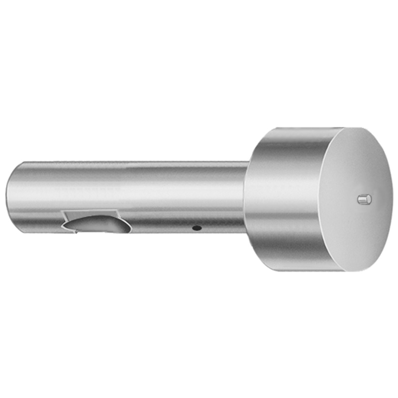
XCDP Coating Ball Lock Ejector Punches - Light Duty, Inch
Ball Lock Ejector Punches - Light Duty, Inch with XCDP coating are precision die components for consistent ball-lock action and dependable part ejection. Built for lighter duty tooling where smooth performance and wear control matter.
- Ball lock punch design helps secure repeatable ejection in die sets
- XCDP coating supports improved wear resistance in press operations
- Manufactured for stable fit to help maintain consistent alignment
- Commonly used for light-duty progressive and transfer die applications
Specifications
114 configurations available
| Tip Shape | D (Shank dia.) (in) | Jektole group | L (Length) (coded inch) | P Dimension (in) | W Dimension (in) | R Dimension (in) |
|---|---|---|---|---|---|---|
| H | 37 (0.3750") | J4 | 250 ~ 450 | 0.376 ~ 0.875 | 0.062 ~ 0.124 | - |
| H | 37 (0.3750") | J4 | 250 ~ 450 | 0.376 ~ 0.875 | 0.125 ~ 0.875 | - |
| H | 50 (0.5000") | J6 | 250 ~ 450 | 0.501 ~ 1.25 | 0.158 ~ 0.187 | - |
| H | 50 (0.5000") | J6 | 250 ~ 450 | 0.501 ~ 1.25 | 0.188 ~ 1.25 | - |
| H | 62 (0.6250") | J6 | 250 ~ 450 | 0.626 ~ 1.5 | 0.25 ~ 1.5 | - |
| H | 62 (0.6250") | J6 | 250 ~ 450 | 0.626 ~ 1.5 | 0.158 ~ 0.249 | - |
| H | 75 (0.7500") | J9 | 250 ~ 450 | 0.751 ~ 1.5 | 0.235 ~ 0.311 | - |
| H | 75 (0.7500") | J9 | 250 ~ 450 | 0.751 ~ 1.5 | 0.312 ~ 1.5 | - |
| H | 87 (0.8750") | J9 | 250 ~ 450 | 0.876 ~ 1.75 | 0.235 ~ 0.374 | - |
| H | 87 (0.8750") | J9 | 250 ~ 450 | 0.876 ~ 1.75 | 0.375 ~ 1.75 | - |
| H | 100 (1.0000") | J9 | 250 ~ 450 | 1.001 ~ 1.75 | 0.235 ~ 0.436 | - |
| H | 100 (1.0000") | J9 | 250 ~ 450 | 1.001 ~ 1.75 | 0.437 ~ 1.75 | - |
| J | 37 (0.3750") | J4 | 250 ~ 450 | 0.376 ~ 0.875 | 0.062 ~ 0.124 | - |
| J | 37 (0.3750") | J4 | 250 ~ 450 | 0.376 ~ 0.875 | 0.125 ~ 0.875 | - |
| J | 50 (0.5000") | J6 | 250 ~ 450 | 0.501 ~ 1.25 | 0.158 ~ 0.187 | - |
| J | 50 (0.5000") | J6 | 250 ~ 450 | 0.501 ~ 1.25 | 0.188 ~ 1.25 | - |
| J | 62 (0.6250") | J6 | 250 ~ 450 | 0.626 ~ 1.5 | 0.25 ~ 1.5 | - |
| J | 62 (0.6250") | J6 | 250 ~ 450 | 0.626 ~ 1.5 | 0.158 ~ 0.249 | - |
| J | 75 (0.7500") | J9 | 250 ~ 450 | 0.751 ~ 1.5 | 0.235 ~ 0.311 | - |
| J | 75 (0.7500") | J9 | 250 ~ 450 | 0.751 ~ 1.5 | 0.312 ~ 1.5 | - |
| J | 87 (0.8750") | J9 | 250 ~ 450 | 0.876 ~ 1.75 | 0.235 ~ 0.374 | - |
| J | 87 (0.8750") | J9 | 250 ~ 450 | 0.876 ~ 1.75 | 0.375 ~ 1.75 | - |
| J | 100 (1.0000") | J9 | 250 ~ 450 | 1.001 ~ 1.75 | 0.235 ~ 0.436 | - |
| J | 100 (1.0000") | J9 | 250 ~ 450 | 1.001 ~ 1.75 | 0.437 ~ 1.75 | - |
| K | 37 (0.3750") | J4 | 250 ~ 450 | 0.376 ~ 0.875 | 0.062 ~ 0.124 | 0.007 ~ 0.4375 |
| K | 37 (0.3750") | J4 | 250 ~ 450 | 0.376 ~ 0.875 | 0.125 ~ 0.875 | 0.007 ~ 0.4375 |
| K | 50 (0.5000") | J6 | 250 ~ 450 | 0.501 ~ 1.25 | 0.158 ~ 0.187 | 0.007 ~ 0.625 |
| K | 50 (0.5000") | J6 | 250 ~ 450 | 0.501 ~ 1.25 | 0.188 ~ 1.25 | 0.007 ~ 0.625 |
| K | 62 (0.6250") | J6 | 250 ~ 450 | 0.626 ~ 1.5 | 0.25 ~ 1.5 | 0.007 ~ 0.75 |
| K | 62 (0.6250") | J6 | 250 ~ 450 | 0.626 ~ 1.5 | 0.158 ~ 0.249 | 0.007 ~ 0.75 |
| K | 75 (0.7500") | J9 | 250 ~ 450 | 0.751 ~ 1.5 | 0.235 ~ 0.311 | 0.007 ~ 0.75 |
| K | 75 (0.7500") | J9 | 250 ~ 450 | 0.751 ~ 1.5 | 0.312 ~ 1.5 | 0.007 ~ 0.75 |
| K | 87 (0.8750") | J9 | 250 ~ 450 | 0.876 ~ 1.75 | 0.235 ~ 0.374 | 0.007 ~ 0.875 |
| K | 87 (0.8750") | J9 | 250 ~ 450 | 0.876 ~ 1.75 | 0.375 ~ 1.75 | 0.007 ~ 0.875 |
| K | 100 (1.0000") | J9 | 250 ~ 450 | 1.001 ~ 1.75 | 0.235 ~ 0.436 | 0.007 ~ 0.875 |
| K | 100 (1.0000") | J9 | 250 ~ 450 | 1.001 ~ 1.75 | 0.437 ~ 1.75 | 0.007 ~ 0.875 |
| L | 37 (0.3750") | J4 | 250 ~ 450 | 0.376 ~ 0.875 | 0.062 ~ 0.124 | - |
| L | 37 (0.3750") | J4 | 250 ~ 450 | 0.376 ~ 0.875 | 0.125 ~ 0.875 | - |
| L | 50 (0.5000") | J6 | 250 ~ 450 | 0.501 ~ 1.25 | 0.158 ~ 0.187 | - |
| L | 50 (0.5000") | J6 | 250 ~ 450 | 0.501 ~ 1.25 | 0.188 ~ 1.25 | - |
| L | 62 (0.6250") | J6 | 250 ~ 450 | 0.626 ~ 1.5 | 0.25 ~ 1.5 | - |
| L | 62 (0.6250") | J6 | 250 ~ 450 | 0.626 ~ 1.5 | 0.158 ~ 0.249 | - |
| L | 75 (0.7500") | J9 | 250 ~ 450 | 0.751 ~ 1.5 | 0.235 ~ 0.311 | - |
| L | 75 (0.7500") | J9 | 250 ~ 450 | 0.751 ~ 1.5 | 0.312 ~ 1.5 | - |
| L | 87 (0.8750") | J9 | 250 ~ 450 | 0.876 ~ 1.75 | 0.235 ~ 0.374 | - |
| L | 87 (0.8750") | J9 | 250 ~ 450 | 0.876 ~ 1.75 | 0.375 ~ 1.75 | - |
| L | 100 (1.0000") | J9 | 250 ~ 450 | 1.001 ~ 1.75 | 0.235 ~ 0.436 | - |
| L | 100 (1.0000") | J9 | 250 ~ 450 | 1.001 ~ 1.75 | 0.437 ~ 1.75 | - |
| N | 37 (0.3750") | J4 | 250 ~ 450 | - | 0.326 ~ 0.758 | - |
| N | 50 (0.5000") | J6 | 250 ~ 450 | - | 0.434 ~ 1.083 | - |
Product Guide
Application Scenarios+
These light-duty ball lock ejector punches are used in injection and press tooling where reliable die-side ejection is required but contact loads are moderate. The ball-lock action helps maintain repeatable coupling to mating components, improving ejection timing consistency across production cycles.
- Progressive/transfer die applications (light duty): Match the punch shank diameter range (0.3750" to 1.0000") and choose a tip shape (H–Z) to suit the die cavity/core layout while supporting stable alignment during part release.
- Thin-wall or precision stamped features: The XCDP coating is selected to help reduce wear at sliding/engagement surfaces, helping maintain smooth ball-lock movement and consistent ejection over time.
- Multi-station assemblies with mixed ejector geometry: Select the coded length (L = 250–450 in inch-coded units) to avoid interference and keep stroke clearance, while the configurable P and W ranges allow adaptation to specific lock-ball engagement dimensions.
Overall, the XCDP-coated variant is suited for tooling that prioritizes controlled wear and dependable ejection performance under light loads.
Material & Process Details+
The provided specification set focuses on geometry and the XCDP coating, but does not list the underlying steel grade or measured hardness (HRC). For material selection, confirm the base steel and coating system from the manufacturer’s technical data sheet for the corresponding series/variants, especially if you need hardening targets for wear and bending resistance.
- Coating role (XCDP): Used to improve surface wear resistance at the ball-lock engagement and sliding interfaces, supporting smoother movement and longer tool life in lighter duty press/injection support tooling.
- Heat treatment: Not specified in the input data—verify whether the punches are provided in a pre-hardened condition or require case/coating-related treatments.
- Trade-offs: Without the base grade and HRC, compare options by target hardness versus toughness: higher hardness typically improves abrasion resistance but can reduce toughness if the tool sees shock or misalignment.
If you share the steel grade and tolerance class for this series, the hardness and heat-treatment guidance can be made fully specific.
Sizing & Selection Guide+
Select dimensions by matching both mechanical clearance and ball-lock engagement geometry to your die cavity/core and mating components. Start with the D (shank dia.) range—0.3750" (37), 0.5000" (50), 0.6250" (62), 0.7500" (75), 0.8750" (87), or 1.0000" (100)—to ensure the punch can be guided without side loading.
- Length selection: Choose the coded L in the range 250–450 (coded inch). Verify stack-up against die thickness and stroke requirements so the ball lock fully engages and ejects without bottoming.
- Engagement geometry (configurable): Match P within the available ranges (0.376–0.875, 0.501–1.25, 0.626–1.5, 0.751–1.5, 0.876–1.75, 1.001–1.75) and set W (0.062–0.867) to your mating lock-ball/coupler dimensions.
- Tip contour: Select Tip Shape (H, J, K, L, N, O, R, V, X, Y, Z) to fit the cavity contact needs and part release surface.
- R (radius) selection: Use the available R ranges (0.007–0.4375, 0.007–0.625, 0.007–0.75, 0.007–0.875) for profile match and stress reduction at contact.
Tolerance/fit guidance depends on the mating part’s tolerance class; confirm the die-side holes or bushings’ spec before finalizing the D and engagement dimensions.
Frequently Asked Questions
Which shank diameter (D) options are available for these light-duty ball lock ejector punches?+
Available D (shank dia.) values are 0.3750" (37), 0.5000" (50), 0.6250" (62), 0.7500" (75), 0.8750" (87), and 1.0000" (100). Select the smallest D that meets your guiding and load needs while maintaining proper alignment in the die set.
How do I choose the coded length (L) to ensure correct stroke and ball-lock engagement?+
The coded L range provided is 250 to 450 (coded inch). Use your die stack-up and required ejection clearance to verify that the punch length allows full engagement of the ball-lock action without bottoming or causing interference in the open position.
What are the configurable ranges for P, W, and R that affect ball-lock engagement geometry?+
P is available in multiple inch ranges (0.376–0.875, 0.501–1.25, 0.626–1.5, 0.751–1.5, 0.876–1.75, 1.001–1.75). W ranges from 0.062 to 0.867, and R ranges include 0.007–0.4375, 0.007–0.625, 0.007–0.75, and 0.007–0.875.
Match these to the mating lock-ball/coupler dimensions in your die design to maintain proper coupling and release behavior.
Which tip shapes (H–Z) should be considered for part release without damaging thin features?+
The tip shape is selectable from H, J, K, L, N, O, R, V, X, Y, Z. Choose the profile that best fits your part contact area and cavity geometry to distribute load and reduce localized stress during ejection.
For die-side compatibility, confirm the tip contour and radius R selected aligns with the cavity relief and any tooling clearances.
What does the XCDP coating improve for light-duty ejection tools?+
This series specifies an XCDP coating, intended to support improved wear resistance at the engagement and sliding surfaces used during ejection cycles. For light-duty progressive/transfer die use, this helps maintain smoother ball-lock movement and reduces wear-related performance drift over time.
To fully validate life targets, confirm the base steel grade and the coating thickness/hardness performance from the manufacturer’s datasheet.
Related Products


Need Custom Specifications?
Our engineering team can help with custom configurations, material selection, and volume pricing.