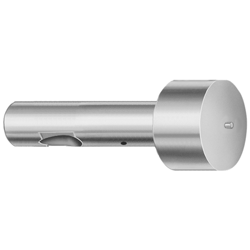
Inch Light Duty Ball Lock Ejector Punches - X-Shaped Tip
Ball Lock ejector punches for inch light duty applications feature an X-shaped tip to improve locating and assist consistent ball lock retention during die operation. Built for dependable ejection in production molds.
- X-shaped tip design helps maintain controlled engagement for stable ejection
- Tooling-grade construction supports repeatable performance under regular die cycling
- Inch-coded light duty punch format supports compatibility with standard punch systems
- Typical use in progressive and transfer tooling where ball lock retention is required
Specifications
114 configurations available
| Tip Shape | D (Shank dia.) (in) | Jektole group | L (Length) (coded inch) | P Dimension (in) | W Dimension (in) | R Dimension (in) |
|---|---|---|---|---|---|---|
| H | 37 (0.3750") | J4 | 250 ~ 450 | 0.376 ~ 0.875 | 0.062 ~ 0.124 | - |
| H | 37 (0.3750") | J4 | 250 ~ 450 | 0.376 ~ 0.875 | 0.125 ~ 0.875 | - |
| H | 50 (0.5000") | J6 | 250 ~ 450 | 0.501 ~ 1.25 | 0.158 ~ 0.187 | - |
| H | 50 (0.5000") | J6 | 250 ~ 450 | 0.501 ~ 1.25 | 0.188 ~ 1.25 | - |
| H | 62 (0.6250") | J6 | 250 ~ 450 | 0.626 ~ 1.5 | 0.25 ~ 1.5 | - |
| H | 62 (0.6250") | J6 | 250 ~ 450 | 0.626 ~ 1.5 | 0.158 ~ 0.249 | - |
| H | 75 (0.7500") | J9 | 250 ~ 450 | 0.751 ~ 1.5 | 0.235 ~ 0.311 | - |
| H | 75 (0.7500") | J9 | 250 ~ 450 | 0.751 ~ 1.5 | 0.312 ~ 1.5 | - |
| H | 87 (0.8750") | J9 | 250 ~ 450 | 0.876 ~ 1.75 | 0.235 ~ 0.374 | - |
| H | 87 (0.8750") | J9 | 250 ~ 450 | 0.876 ~ 1.75 | 0.375 ~ 1.75 | - |
| H | 100 (1.0000") | J9 | 250 ~ 450 | 1.001 ~ 1.75 | 0.235 ~ 0.436 | - |
| H | 100 (1.0000") | J9 | 250 ~ 450 | 1.001 ~ 1.75 | 0.437 ~ 1.75 | - |
| J | 37 (0.3750") | J4 | 250 ~ 450 | 0.376 ~ 0.875 | 0.062 ~ 0.124 | - |
| J | 37 (0.3750") | J4 | 250 ~ 450 | 0.376 ~ 0.875 | 0.125 ~ 0.875 | - |
| J | 50 (0.5000") | J6 | 250 ~ 450 | 0.501 ~ 1.25 | 0.158 ~ 0.187 | - |
| J | 50 (0.5000") | J6 | 250 ~ 450 | 0.501 ~ 1.25 | 0.188 ~ 1.25 | - |
| J | 62 (0.6250") | J6 | 250 ~ 450 | 0.626 ~ 1.5 | 0.25 ~ 1.5 | - |
| J | 62 (0.6250") | J6 | 250 ~ 450 | 0.626 ~ 1.5 | 0.158 ~ 0.249 | - |
| J | 75 (0.7500") | J9 | 250 ~ 450 | 0.751 ~ 1.5 | 0.235 ~ 0.311 | - |
| J | 75 (0.7500") | J9 | 250 ~ 450 | 0.751 ~ 1.5 | 0.312 ~ 1.5 | - |
| J | 87 (0.8750") | J9 | 250 ~ 450 | 0.876 ~ 1.75 | 0.235 ~ 0.374 | - |
| J | 87 (0.8750") | J9 | 250 ~ 450 | 0.876 ~ 1.75 | 0.375 ~ 1.75 | - |
| J | 100 (1.0000") | J9 | 250 ~ 450 | 1.001 ~ 1.75 | 0.235 ~ 0.436 | - |
| J | 100 (1.0000") | J9 | 250 ~ 450 | 1.001 ~ 1.75 | 0.437 ~ 1.75 | - |
| K | 37 (0.3750") | J4 | 250 ~ 450 | 0.376 ~ 0.875 | 0.062 ~ 0.124 | 0.007 ~ 0.4375 |
| K | 37 (0.3750") | J4 | 250 ~ 450 | 0.376 ~ 0.875 | 0.125 ~ 0.875 | 0.007 ~ 0.4375 |
| K | 50 (0.5000") | J6 | 250 ~ 450 | 0.501 ~ 1.25 | 0.158 ~ 0.187 | 0.007 ~ 0.625 |
| K | 50 (0.5000") | J6 | 250 ~ 450 | 0.501 ~ 1.25 | 0.188 ~ 1.25 | 0.007 ~ 0.625 |
| K | 62 (0.6250") | J6 | 250 ~ 450 | 0.626 ~ 1.5 | 0.25 ~ 1.5 | 0.007 ~ 0.75 |
| K | 62 (0.6250") | J6 | 250 ~ 450 | 0.626 ~ 1.5 | 0.158 ~ 0.249 | 0.007 ~ 0.75 |
| K | 75 (0.7500") | J9 | 250 ~ 450 | 0.751 ~ 1.5 | 0.235 ~ 0.311 | 0.007 ~ 0.75 |
| K | 75 (0.7500") | J9 | 250 ~ 450 | 0.751 ~ 1.5 | 0.312 ~ 1.5 | 0.007 ~ 0.75 |
| K | 87 (0.8750") | J9 | 250 ~ 450 | 0.876 ~ 1.75 | 0.235 ~ 0.374 | 0.007 ~ 0.875 |
| K | 87 (0.8750") | J9 | 250 ~ 450 | 0.876 ~ 1.75 | 0.375 ~ 1.75 | 0.007 ~ 0.875 |
| K | 100 (1.0000") | J9 | 250 ~ 450 | 1.001 ~ 1.75 | 0.235 ~ 0.436 | 0.007 ~ 0.875 |
| K | 100 (1.0000") | J9 | 250 ~ 450 | 1.001 ~ 1.75 | 0.437 ~ 1.75 | 0.007 ~ 0.875 |
| L | 37 (0.3750") | J4 | 250 ~ 450 | 0.376 ~ 0.875 | 0.062 ~ 0.124 | - |
| L | 37 (0.3750") | J4 | 250 ~ 450 | 0.376 ~ 0.875 | 0.125 ~ 0.875 | - |
| L | 50 (0.5000") | J6 | 250 ~ 450 | 0.501 ~ 1.25 | 0.158 ~ 0.187 | - |
| L | 50 (0.5000") | J6 | 250 ~ 450 | 0.501 ~ 1.25 | 0.188 ~ 1.25 | - |
| L | 62 (0.6250") | J6 | 250 ~ 450 | 0.626 ~ 1.5 | 0.25 ~ 1.5 | - |
| L | 62 (0.6250") | J6 | 250 ~ 450 | 0.626 ~ 1.5 | 0.158 ~ 0.249 | - |
| L | 75 (0.7500") | J9 | 250 ~ 450 | 0.751 ~ 1.5 | 0.235 ~ 0.311 | - |
| L | 75 (0.7500") | J9 | 250 ~ 450 | 0.751 ~ 1.5 | 0.312 ~ 1.5 | - |
| L | 87 (0.8750") | J9 | 250 ~ 450 | 0.876 ~ 1.75 | 0.235 ~ 0.374 | - |
| L | 87 (0.8750") | J9 | 250 ~ 450 | 0.876 ~ 1.75 | 0.375 ~ 1.75 | - |
| L | 100 (1.0000") | J9 | 250 ~ 450 | 1.001 ~ 1.75 | 0.235 ~ 0.436 | - |
| L | 100 (1.0000") | J9 | 250 ~ 450 | 1.001 ~ 1.75 | 0.437 ~ 1.75 | - |
| N | 37 (0.3750") | J4 | 250 ~ 450 | - | 0.326 ~ 0.758 | - |
| N | 50 (0.5000") | J6 | 250 ~ 450 | - | 0.434 ~ 1.083 | - |
Product Guide
Application Scenarios+
These inch light-duty ball lock ejector punches are used in injection and die-casting tooling where repeatable ball lock retention and ejection are required during regular cycling. The X-shaped tip supports controlled engagement, helping the ball lock system maintain consistent contact under load and during stroke reversals.
- Progressive/transfer die work for small parts: Suitable when the die set needs dependable ejection while keeping punch-to-punch location stable; the X-shaped tip assists consistent retention so ejection is predictable.
- Thin-wall die components and die workpieces: The light-duty inch format supports compatibility with standard inch punch systems, reducing integration issues when upgrading or servicing existing tooling.
- Ball-lock retention in multi-cavity tooling: Works well where multiple stations require uniform behavior; stable retention improves ejection reliability across frequent cycles.
Material & Process Details+
Material and heat-treatment details are not provided in the available specifications for this item. For ball lock ejector punches in general, tool steel is typically selected for a balance of wear resistance (to resist tip and guide contact) and toughness (to limit chipping during repeated cycling). Heat treatment is commonly implemented as quench-and-temper for toughness or as surface hardening (e.g., nitriding) when additional wear resistance is required.
When comparing variants, the practical difference between tip shapes (including the X-shaped tip) is usually functional geometry rather than alloy; however, final hardness and wear performance are primarily determined by the steel grade and the specified heat-treatment route. For exact hardness (HRC) and process state (pre-hardened vs. quenched & tempered vs. nitrided), confirm with the technical data sheet or request from the supplier.
Sizing & Selection Guide+
Select the correct punch by matching the inch shank diameter and length to your cavity/core and guide requirements. The D (shank dia.) is available at 0.3750, 0.5000, 0.6250, 0.7500, 0.8750, and 1.0000 in. Choose L (length, coded inch) within the fixed range of 250 to 450 to ensure full travel without bottoming.
Then verify the tip geometry for retention clearance and engagement. The P dimension is variable across multiple bands (0.376–0.875, 0.501–1.25, 0.626–1.5, 0.751–1.5, 0.876–1.75, 1.001–1.75 in), while the W dimension ranges 0.062–0.867 in. The R dimension provides tip/edge radius options (0.007–0.4375, 0.007–0.625, 0.007–0.75, 0.007–0.875 in) depending on configuration.
- Fit/tolerance: use your punch bore and ball-lock mechanism tolerances to confirm clearance; ball-lock retention performance depends on consistent engagement geometry.
- Configurable vs fixed: Tip shape is variable (H, J, K, L, N, O, R, V, X, Y, Z), while L is fixed by the coded inch range.
Frequently Asked Questions
How do I choose the correct D (shank dia.) for ball-lock punch compatibility with my guide system?+
Select D (shank dia.) to match your guide and bore sizing. This product lists D options of 0.3750, 0.5000, 0.6250, 0.7500, 0.8750, and 1.0000 in.
Use your existing guide clearance/tolerance to confirm fit so the punch can slide freely while still providing stable engagement for retention.
What tip shape should be selected when stable ball-lock retention and consistent ejection are required?+
For this variant, the X-shaped tip is intended to improve locating and assist consistent ball lock retention during die operation. The geometry supports controlled engagement, which helps maintain predictable ejection behavior under regular cycling.
If your die requires another engagement profile, you can compare against other available tip shapes (H, J, K, L, N, O, R, V, X, Y, Z) while keeping D and length matched to your tooling.
How do I match L (coded inch length) to prevent bottoming while ensuring full stroke ejection?+
L is fixed to a coded-inch range of 250 to 450. Choose a length that allows complete ejection travel without the punch contacting the end of the cavity/core travel.
When setting stroke, account for ball-lock mechanism movement so the X-shaped tip completes engagement before the ejection phase.
Which P, W, and R dimensions control the ball-lock engagement geometry on this punch?+
The engagement profile is defined by the P dimension (0.376–0.875, 0.501–1.25, 0.626–1.5, 0.751–1.5, 0.876–1.75, 1.001–1.75 in), W (0.062–0.867 in), and R (0.007–0.4375, 0.007–0.625, 0.007–0.75, 0.007–0.875 in).
For reliable retention, verify these values against your ball-lock housing and clearance requirements in the die assembly.
What does the Jektole group (J4/J6/J9) indicate for tool design selection?+
The product is grouped as J4, J6, or J9 in the Jektole group field. Use the same group designation as your existing tooling system to maintain dimensional and functional compatibility.
If you are redesigning, confirm group-to-geometry relationships in the technical drawings for the selected P/W/R configuration.
Related Products


Need Custom Specifications?
Our engineering team can help with custom configurations, material selection, and volume pricing.