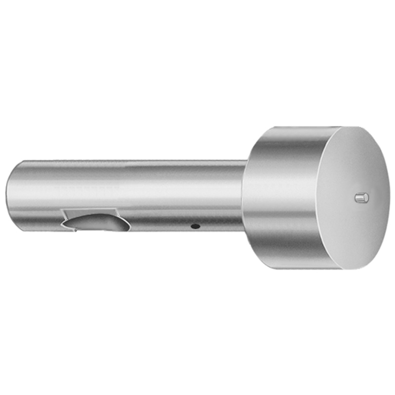
Point Larger than Shank Ball Lock Punches - Light Duty, Inch, XNP Coating
Point Larger than Shank Ball Lock Punches (XNP coating) are designed for light-duty inch mold ejection, where the punch point exceeds the shank size for controlled engagement and consistent part release. The XNP surface treatment helps maintain tooling stability under repeated press cycles.
- Point larger than shank geometry supports reliable ball lock engagement
- XNP coating promotes wear resistance for stable ejection performance
- Light-duty inch configuration simplifies selection for compatible tooling sets
- Suitable for mold assemblies requiring ball lock punch inserts and blanks
Specifications
114 configurations available
| Tip Shape | D (Shank dia.) (in) | Jektole group | L (Length) (coded inch) | P Dimension (in) | W Dimension (in) | R Dimension (in) |
|---|---|---|---|---|---|---|
| H | 37 (0.3750") | J4 | 250 ~ 450 | 0.376 ~ 0.875 | 0.062 ~ 0.124 | - |
| H | 37 (0.3750") | J4 | 250 ~ 450 | 0.376 ~ 0.875 | 0.125 ~ 0.875 | - |
| H | 50 (0.5000") | J6 | 250 ~ 450 | 0.501 ~ 1.25 | 0.158 ~ 0.187 | - |
| H | 50 (0.5000") | J6 | 250 ~ 450 | 0.501 ~ 1.25 | 0.188 ~ 1.25 | - |
| H | 62 (0.6250") | J6 | 250 ~ 450 | 0.626 ~ 1.5 | 0.25 ~ 1.5 | - |
| H | 62 (0.6250") | J6 | 250 ~ 450 | 0.626 ~ 1.5 | 0.158 ~ 0.249 | - |
| H | 75 (0.7500") | J9 | 250 ~ 450 | 0.751 ~ 1.5 | 0.235 ~ 0.311 | - |
| H | 75 (0.7500") | J9 | 250 ~ 450 | 0.751 ~ 1.5 | 0.312 ~ 1.5 | - |
| H | 87 (0.8750") | J9 | 250 ~ 450 | 0.876 ~ 1.75 | 0.235 ~ 0.374 | - |
| H | 87 (0.8750") | J9 | 250 ~ 450 | 0.876 ~ 1.75 | 0.375 ~ 1.75 | - |
| H | 100 (1.0000") | J9 | 250 ~ 450 | 1.001 ~ 1.75 | 0.235 ~ 0.436 | - |
| H | 100 (1.0000") | J9 | 250 ~ 450 | 1.001 ~ 1.75 | 0.437 ~ 1.75 | - |
| J | 37 (0.3750") | J4 | 250 ~ 450 | 0.376 ~ 0.875 | 0.062 ~ 0.124 | - |
| J | 37 (0.3750") | J4 | 250 ~ 450 | 0.376 ~ 0.875 | 0.125 ~ 0.875 | - |
| J | 50 (0.5000") | J6 | 250 ~ 450 | 0.501 ~ 1.25 | 0.158 ~ 0.187 | - |
| J | 50 (0.5000") | J6 | 250 ~ 450 | 0.501 ~ 1.25 | 0.188 ~ 1.25 | - |
| J | 62 (0.6250") | J6 | 250 ~ 450 | 0.626 ~ 1.5 | 0.25 ~ 1.5 | - |
| J | 62 (0.6250") | J6 | 250 ~ 450 | 0.626 ~ 1.5 | 0.158 ~ 0.249 | - |
| J | 75 (0.7500") | J9 | 250 ~ 450 | 0.751 ~ 1.5 | 0.235 ~ 0.311 | - |
| J | 75 (0.7500") | J9 | 250 ~ 450 | 0.751 ~ 1.5 | 0.312 ~ 1.5 | - |
| J | 87 (0.8750") | J9 | 250 ~ 450 | 0.876 ~ 1.75 | 0.235 ~ 0.374 | - |
| J | 87 (0.8750") | J9 | 250 ~ 450 | 0.876 ~ 1.75 | 0.375 ~ 1.75 | - |
| J | 100 (1.0000") | J9 | 250 ~ 450 | 1.001 ~ 1.75 | 0.235 ~ 0.436 | - |
| J | 100 (1.0000") | J9 | 250 ~ 450 | 1.001 ~ 1.75 | 0.437 ~ 1.75 | - |
| K | 37 (0.3750") | J4 | 250 ~ 450 | 0.376 ~ 0.875 | 0.062 ~ 0.124 | 0.007 ~ 0.4375 |
| K | 37 (0.3750") | J4 | 250 ~ 450 | 0.376 ~ 0.875 | 0.125 ~ 0.875 | 0.007 ~ 0.4375 |
| K | 50 (0.5000") | J6 | 250 ~ 450 | 0.501 ~ 1.25 | 0.158 ~ 0.187 | 0.007 ~ 0.625 |
| K | 50 (0.5000") | J6 | 250 ~ 450 | 0.501 ~ 1.25 | 0.188 ~ 1.25 | 0.007 ~ 0.625 |
| K | 62 (0.6250") | J6 | 250 ~ 450 | 0.626 ~ 1.5 | 0.25 ~ 1.5 | 0.007 ~ 0.75 |
| K | 62 (0.6250") | J6 | 250 ~ 450 | 0.626 ~ 1.5 | 0.158 ~ 0.249 | 0.007 ~ 0.75 |
| K | 75 (0.7500") | J9 | 250 ~ 450 | 0.751 ~ 1.5 | 0.235 ~ 0.311 | 0.007 ~ 0.75 |
| K | 75 (0.7500") | J9 | 250 ~ 450 | 0.751 ~ 1.5 | 0.312 ~ 1.5 | 0.007 ~ 0.75 |
| K | 87 (0.8750") | J9 | 250 ~ 450 | 0.876 ~ 1.75 | 0.235 ~ 0.374 | 0.007 ~ 0.875 |
| K | 87 (0.8750") | J9 | 250 ~ 450 | 0.876 ~ 1.75 | 0.375 ~ 1.75 | 0.007 ~ 0.875 |
| K | 100 (1.0000") | J9 | 250 ~ 450 | 1.001 ~ 1.75 | 0.235 ~ 0.436 | 0.007 ~ 0.875 |
| K | 100 (1.0000") | J9 | 250 ~ 450 | 1.001 ~ 1.75 | 0.437 ~ 1.75 | 0.007 ~ 0.875 |
| L | 37 (0.3750") | J4 | 250 ~ 450 | 0.376 ~ 0.875 | 0.062 ~ 0.124 | - |
| L | 37 (0.3750") | J4 | 250 ~ 450 | 0.376 ~ 0.875 | 0.125 ~ 0.875 | - |
| L | 50 (0.5000") | J6 | 250 ~ 450 | 0.501 ~ 1.25 | 0.158 ~ 0.187 | - |
| L | 50 (0.5000") | J6 | 250 ~ 450 | 0.501 ~ 1.25 | 0.188 ~ 1.25 | - |
| L | 62 (0.6250") | J6 | 250 ~ 450 | 0.626 ~ 1.5 | 0.25 ~ 1.5 | - |
| L | 62 (0.6250") | J6 | 250 ~ 450 | 0.626 ~ 1.5 | 0.158 ~ 0.249 | - |
| L | 75 (0.7500") | J9 | 250 ~ 450 | 0.751 ~ 1.5 | 0.235 ~ 0.311 | - |
| L | 75 (0.7500") | J9 | 250 ~ 450 | 0.751 ~ 1.5 | 0.312 ~ 1.5 | - |
| L | 87 (0.8750") | J9 | 250 ~ 450 | 0.876 ~ 1.75 | 0.235 ~ 0.374 | - |
| L | 87 (0.8750") | J9 | 250 ~ 450 | 0.876 ~ 1.75 | 0.375 ~ 1.75 | - |
| L | 100 (1.0000") | J9 | 250 ~ 450 | 1.001 ~ 1.75 | 0.235 ~ 0.436 | - |
| L | 100 (1.0000") | J9 | 250 ~ 450 | 1.001 ~ 1.75 | 0.437 ~ 1.75 | - |
| N | 37 (0.3750") | J4 | 250 ~ 450 | - | 0.326 ~ 0.758 | - |
| N | 50 (0.5000") | J6 | 250 ~ 450 | - | 0.434 ~ 1.083 | - |
Product Guide
Application Scenarios+
These light-duty, inch-format ball lock punch points are used in injection mold ejection systems where repeatable engagement and controlled release are critical. The key geometry—the point larger than the shank—supports stable ball lock interaction, helping prevent inconsistent positioning during press cycles.
- Automotive and appliances connector/trim molds: Ideal for ejector setups that use ball lock punch inserts, where the punch needs reliable engagement while keeping maintenance intervals manageable. The light-duty configuration and inch sizing simplify integration with compatible tooling sets.
- General consumer product housings: Suitable for molds requiring consistent ejection without aggressive load requirements. The point-over-shank design improves controlled engagement, supporting repeatable part release.
- Maintenance-friendly multi-cavity tooling: When punch points must be swapped or grouped by jektole group compatibility, these variants help standardize ejection behavior across cavities.
The XNP surface coating is selected to support stable punch performance under frequent ejection cycles by improving surface durability.
Material & Process Details+
The provided specification set identifies this punch as a light-duty inch ball lock point with an XNP coating, but it does not list the underlying base steel grade or explicit heat-treatment/HRC values. As a result, the exact hardness target and any quench & temper or nitriding details cannot be stated from the available data.
- XNP coating role: The coating is intended to enhance wear resistance and maintain stable contact behavior during repeated press cycles.
- Performance trade-off: Coated surfaces generally improve wear life, while the base material toughness still governs resistance to chipping under off-axis loading.
For engineers comparing alternatives, prioritize confirming the base steel grade, expected hardness (HRC), and the coating system compatibility with your ejection load and lubrication conditions.
Sizing & Selection Guide+
Selection is driven by matching the punch’s coded length and dimensional compatibility with the ball lock ejection system geometry. This series provides a fixed L (length) coded inch range of 250 to 450, and variable shank/pin dimensions in inch.
- Shank diameter D (in): choose from 0.3750, 0.5000, 0.6250, 0.7500, 0.8750, 1.0000.
- Point geometry P (in): select the range that fits your engagement requirement: 0.376–0.875, 0.501–1.25, 0.626–1.5, 0.751–1.5, 0.876–1.75, or 1.001–1.75.
- Tip shape and functional clearance: match Tip Shape (H, J, K, L, N, O, R, V, X, Y, Z) to your interface profile, and verify W (0.062–0.867) and R (0.007–0.4375, 0.007–0.625, 0.007–0.75, 0.007–0.875) to avoid interference.
Because tolerances are not provided in the dataset, confirm allowable clearance/interference by referencing your ball lock assembly design tolerances and any vendor interface drawings for the jektole group (J4, J6, J9).
Frequently Asked Questions
How do I select the correct punch dimensions for a ball lock ejection interface when the point is larger than the shank?+
Which tip shapes (H, J, K, etc.) should be used to avoid engagement inconsistency in light-duty inch molds?+
What are the coating-related expectations for wear resistance in high-cycle ejection?+
How does the fixed length code range (L = 250–450) affect cavity/core design choices?+
Can I use this light-duty inch ball lock punch point in place of heavier-duty steel options?+
Related Products


Need Custom Specifications?
Our engineering team can help with custom configurations, material selection, and volume pricing.