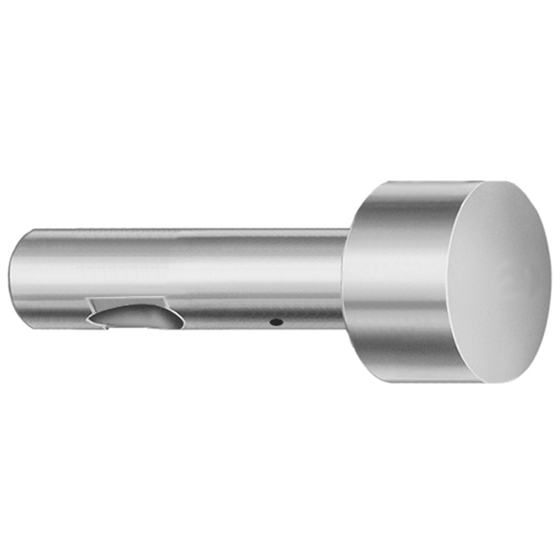
DAYTON Point Larger than Shank Ball Lock Punches - Light Duty, Inch, XCN Coating
Point Larger than Shank Ball Lock Punches (DAYTON, XCN coating) for light duty applications use a larger contact point to support consistent ball lock ejection and alignment during repeated operations. Inch-size selection helps match common tooling setups.
- Point larger than shank geometry improves ball lock stability during ejection
- XCN coating supports wear resistance for longer punch life in production
- Inch-coded construction supports straightforward selection for standard tooling systems
- Suitable for press tooling where light duty ball lock punch performance is required
Specifications
114 configurations available
| Tip Shape | D (Shank dia.) (in) | L (Length) (coded inch) | P Dimension (in) | W Dimension (in) | R Dimension (in) |
|---|---|---|---|---|---|
| H | 37 (0.3750") | 250 ~ 450 | 0.376 ~ 0.875 | 0.062 ~ 0.124 | - |
| H | 37 (0.3750") | 250 ~ 450 | 0.376 ~ 0.875 | 0.125 ~ 0.875 | - |
| H | 50 (0.5000") | 250 ~ 450 | 0.501 ~ 1.25 | 0.158 ~ 0.187 | - |
| H | 50 (0.5000") | 250 ~ 450 | 0.501 ~ 1.25 | 0.188 ~ 1.25 | - |
| H | 62 (0.6250") | 250 ~ 450 | 0.626 ~ 1.5 | 0.25 ~ 1.5 | - |
| H | 62 (0.6250") | 250 ~ 450 | 0.626 ~ 1.5 | 0.158 ~ 0.249 | - |
| H | 75 (0.7500") | 250 ~ 450 | 0.751 ~ 1.5 | 0.235 ~ 0.311 | - |
| H | 75 (0.7500") | 250 ~ 450 | 0.751 ~ 1.5 | 0.312 ~ 1.5 | - |
| H | 87 (0.8750") | 250 ~ 450 | 0.876 ~ 1.75 | 0.235 ~ 0.374 | - |
| H | 87 (0.8750") | 250 ~ 450 | 0.876 ~ 1.75 | 0.375 ~ 1.75 | - |
| H | 100 (1.0000") | 250 ~ 450 | 1.001 ~ 1.75 | 0.235 ~ 0.436 | - |
| H | 100 (1.0000") | 250 ~ 450 | 1.001 ~ 1.75 | 0.437 ~ 1.75 | - |
| J | 37 (0.3750") | 250 ~ 450 | 0.376 ~ 0.875 | 0.062 ~ 0.124 | - |
| J | 37 (0.3750") | 250 ~ 450 | 0.376 ~ 0.875 | 0.125 ~ 0.875 | - |
| J | 50 (0.5000") | 250 ~ 450 | 0.501 ~ 1.25 | 0.158 ~ 0.187 | - |
| J | 50 (0.5000") | 250 ~ 450 | 0.501 ~ 1.25 | 0.188 ~ 1.25 | - |
| J | 62 (0.6250") | 250 ~ 450 | 0.626 ~ 1.5 | 0.25 ~ 1.5 | - |
| J | 62 (0.6250") | 250 ~ 450 | 0.626 ~ 1.5 | 0.158 ~ 0.249 | - |
| J | 75 (0.7500") | 250 ~ 450 | 0.751 ~ 1.5 | 0.235 ~ 0.311 | - |
| J | 75 (0.7500") | 250 ~ 450 | 0.751 ~ 1.5 | 0.312 ~ 1.5 | - |
| J | 87 (0.8750") | 250 ~ 450 | 0.876 ~ 1.75 | 0.235 ~ 0.374 | - |
| J | 87 (0.8750") | 250 ~ 450 | 0.876 ~ 1.75 | 0.375 ~ 1.75 | - |
| J | 100 (1.0000") | 250 ~ 450 | 1.001 ~ 1.75 | 0.235 ~ 0.436 | - |
| J | 100 (1.0000") | 250 ~ 450 | 1.001 ~ 1.75 | 0.437 ~ 1.75 | - |
| K | 37 (0.3750") | 250 ~ 450 | 0.376 ~ 0.875 | 0.062 ~ 0.124 | 0.007 ~ 0.4375 |
| K | 37 (0.3750") | 250 ~ 450 | 0.376 ~ 0.875 | 0.125 ~ 0.875 | 0.007 ~ 0.4375 |
| K | 50 (0.5000") | 250 ~ 450 | 0.501 ~ 1.25 | 0.158 ~ 0.187 | 0.007 ~ 0.625 |
| K | 50 (0.5000") | 250 ~ 450 | 0.501 ~ 1.25 | 0.188 ~ 1.25 | 0.007 ~ 0.625 |
| K | 62 (0.6250") | 250 ~ 450 | 0.626 ~ 1.5 | 0.25 ~ 1.5 | 0.007 ~ 0.75 |
| K | 62 (0.6250") | 250 ~ 450 | 0.626 ~ 1.5 | 0.158 ~ 0.249 | 0.007 ~ 0.75 |
| K | 75 (0.7500") | 250 ~ 450 | 0.751 ~ 1.5 | 0.235 ~ 0.311 | 0.007 ~ 0.75 |
| K | 75 (0.7500") | 250 ~ 450 | 0.751 ~ 1.5 | 0.312 ~ 1.5 | 0.007 ~ 0.75 |
| K | 87 (0.8750") | 250 ~ 450 | 0.876 ~ 1.75 | 0.235 ~ 0.374 | 0.007 ~ 0.875 |
| K | 87 (0.8750") | 250 ~ 450 | 0.876 ~ 1.75 | 0.375 ~ 1.75 | 0.007 ~ 0.875 |
| K | 100 (1.0000") | 250 ~ 450 | 1.001 ~ 1.75 | 0.235 ~ 0.436 | 0.007 ~ 0.875 |
| K | 100 (1.0000") | 250 ~ 450 | 1.001 ~ 1.75 | 0.437 ~ 1.75 | 0.007 ~ 0.875 |
| L | 37 (0.3750") | 250 ~ 450 | 0.376 ~ 0.875 | 0.062 ~ 0.124 | - |
| L | 37 (0.3750") | 250 ~ 450 | 0.376 ~ 0.875 | 0.125 ~ 0.875 | - |
| L | 50 (0.5000") | 250 ~ 450 | 0.501 ~ 1.25 | 0.158 ~ 0.187 | - |
| L | 50 (0.5000") | 250 ~ 450 | 0.501 ~ 1.25 | 0.188 ~ 1.25 | - |
| L | 62 (0.6250") | 250 ~ 450 | 0.626 ~ 1.5 | 0.25 ~ 1.5 | - |
| L | 62 (0.6250") | 250 ~ 450 | 0.626 ~ 1.5 | 0.158 ~ 0.249 | - |
| L | 75 (0.7500") | 250 ~ 450 | 0.751 ~ 1.5 | 0.235 ~ 0.311 | - |
| L | 75 (0.7500") | 250 ~ 450 | 0.751 ~ 1.5 | 0.312 ~ 1.5 | - |
| L | 87 (0.8750") | 250 ~ 450 | 0.876 ~ 1.75 | 0.235 ~ 0.374 | - |
| L | 87 (0.8750") | 250 ~ 450 | 0.876 ~ 1.75 | 0.375 ~ 1.75 | - |
| L | 100 (1.0000") | 250 ~ 450 | 1.001 ~ 1.75 | 0.235 ~ 0.436 | - |
| L | 100 (1.0000") | 250 ~ 450 | 1.001 ~ 1.75 | 0.437 ~ 1.75 | - |
| N | 37 (0.3750") | 250 ~ 450 | - | 0.326 ~ 0.758 | - |
| N | 50 (0.5000") | 250 ~ 450 | - | 0.434 ~ 1.083 | - |
Product Guide
Application Scenarios+
This light-duty ball lock punch variant is used in injection mold tooling where repeated ejector actuation must stay stable, especially in compact alignment setups.
- Automotive connector and sensor housings: The larger-than-shank contact point helps maintain ball-lock alignment and smooth ejection, reducing the risk of sticking or misalignment during frequent press cycles.
- Appliance and consumer part tooling: When lighter load conditions are expected, the point larger-than-shank geometry supports consistent ball lock retention/release while simplifying setup for standard inch-based tooling components.
- Assembly fixtures with ejection modules: The XCN coating is suited for extended production runs by improving surface wear resistance at the sliding/contact areas.
Overall, the inch sizing options and the enlarged point-to-shank relationship make this configuration a strong fit for mold bases and ejector systems that prioritize reliable ball-lock function under light duty conditions.
Material & Process Details+
The provided specifications identify this DAYTON punch configuration as XCN coated for light duty applications, but they do not list the underlying steel grade or heat treatment state. As such, hardness (HRC) and the exact base steel temper/quenched condition cannot be confirmed from the available data.
- XCN coating: typically selected to improve wear resistance at the punch’s contact and sliding surfaces, which can extend service life in repetitive ejection cycles.
- Trade-off: higher wear resistance coatings generally improve run time, while the base material toughness remains a critical factor for resistance to chipping under shock loads.
If you share the steel grade or drawing for this series, we can map it to the equivalent (e.g., H13, D2, M2 families) and specify expected hardness and heat-treatment limits for more precise engineering selection.
Sizing & Selection Guide+
Select dimensions by matching the punch’s shank diameter and overall geometry to your mold core/cavity ball lock system and the corresponding pocket dimensions.
- Shank diameter (D): choose from 0.3750" to 1.0000" (0.3750, 0.5000, 0.6250, 0.7500, 0.8750, 1.0000 in) to fit the ball-lock guide and prevent lateral play.
- Length (L): fixed coded inch range 250 to 450—use this to reach through the required mold thickness and to position the contact point correctly.
- Point/interface geometry: confirm P and W within available variable ranges (P: 0.376–0.875, 0.501–1.25, 0.626–1.5, 0.751–1.5, 0.876–1.75, 1.001–1.75; W: 0.062–0.867) and verify the tip radius R (R: 0.007–0.4375 up to 0.007–0.875 depending on the set).
Use the mold drawing’s tolerances for the mating ball/lock pocket, aiming for minimal clearance to maintain alignment. If your standard uses fixed inch components, selecting the inch-coded D and L ranges helps avoid rework.
Frequently Asked Questions
How do I choose the shank diameter (D) for a ball-lock punch in an inch-based mold?+
Use the available D options: 0.3750", 0.5000", 0.6250", 0.7500", 0.8750", or 1.0000". Match D to the guide bore and ball-lock pocket alignment requirements so the punch runs with minimal lateral clearance during ejection. Verify that your mating component tolerances provide enough clearance for assembly while preventing wobble under load.
What length range (L) should I target to position the ball-lock point correctly through the mold stack?+
This series uses a coded inch L range of 250 to 450. Select L based on mold thickness and the required stroke so the enlarged contact point engages the ball-lock mechanism at the correct depth. Confirm that your ejector actuation travel leaves adequate overrun/clearance to avoid partial engagement.
When designing for ball-lock stability, how does the larger-than-shank point geometry affect retention and ejection?+
The defining feature is a point larger than shank design, which improves ball-lock stability during ejection and helps maintain alignment under repeated operations. In practice, this can reduce the likelihood of sticking or misalignment when the ejector cycles frequently. You still need to size P/W/R so the point profile matches the mating pocket geometry.
What coating does this punch use, and what wear benefit should I expect for light-duty cycles?+
This DAYTON punch variant is specified with XCN coating. The intent is to improve wear resistance at the contact/sliding surfaces, supporting longer punch life for light duty ball-lock ejection. If you provide cycle count and load conditions, we can help you assess whether coating-only performance meets your life target.
Which P, W, and R ranges are available, and how do they map to the tip profile needed in the mold?+
The series provides variable ranges for P, W, and R. Choose P within the listed inch ranges (e.g., 0.376–0.875, 0.501–1.25, up to 1.001–1.75), W within 0.062–0.867, and R within the listed limits (e.g., up to 0.007–0.875 depending on the configuration). Validate against your ball-lock pocket/tip profile drawing to ensure proper engagement without excessive clearance.
Related Products


Need Custom Specifications?
Our engineering team can help with custom configurations, material selection, and volume pricing.