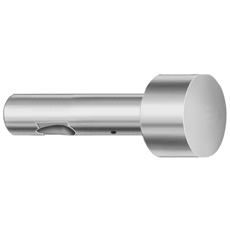
Light Duty X Tip Point Larger than Shank Ball Lock Punches
Point larger than shank ball lock punches are designed for light duty applications, featuring an X tip profile and an enlarged point for reliable locking and feeding. The XN DayTride® coating helps reduce wear and supports consistent punch performance in production cycles.
- Built for light duty ball lock punch stations with enlarged point vs shank
- Wear-resistant XN DayTride® coating improves durability under repeated strokes
- Inch format punch design to match standard tooling workflows in North America
- Suitable for die/punch operations where stable ball lock retention is required
Specifications
114 configurations available
| Tip Shape | D (Shank dia.) (in) | L (Length) (coded inch) | P Dimension (in) | W Dimension (in) | R Dimension (in) |
|---|---|---|---|---|---|
| H | 37 (0.3750") | 250 ~ 450 | 0.376 ~ 0.875 | 0.062 ~ 0.124 | - |
| H | 37 (0.3750") | 250 ~ 450 | 0.376 ~ 0.875 | 0.125 ~ 0.875 | - |
| H | 50 (0.5000") | 250 ~ 450 | 0.501 ~ 1.25 | 0.158 ~ 0.187 | - |
| H | 50 (0.5000") | 250 ~ 450 | 0.501 ~ 1.25 | 0.188 ~ 1.25 | - |
| H | 62 (0.6250") | 250 ~ 450 | 0.626 ~ 1.5 | 0.25 ~ 1.5 | - |
| H | 62 (0.6250") | 250 ~ 450 | 0.626 ~ 1.5 | 0.158 ~ 0.249 | - |
| H | 75 (0.7500") | 250 ~ 450 | 0.751 ~ 1.5 | 0.235 ~ 0.311 | - |
| H | 75 (0.7500") | 250 ~ 450 | 0.751 ~ 1.5 | 0.312 ~ 1.5 | - |
| H | 87 (0.8750") | 250 ~ 450 | 0.876 ~ 1.75 | 0.235 ~ 0.374 | - |
| H | 87 (0.8750") | 250 ~ 450 | 0.876 ~ 1.75 | 0.375 ~ 1.75 | - |
| H | 100 (1.0000") | 250 ~ 450 | 1.001 ~ 1.75 | 0.235 ~ 0.436 | - |
| H | 100 (1.0000") | 250 ~ 450 | 1.001 ~ 1.75 | 0.437 ~ 1.75 | - |
| J | 37 (0.3750") | 250 ~ 450 | 0.376 ~ 0.875 | 0.062 ~ 0.124 | - |
| J | 37 (0.3750") | 250 ~ 450 | 0.376 ~ 0.875 | 0.125 ~ 0.875 | - |
| J | 50 (0.5000") | 250 ~ 450 | 0.501 ~ 1.25 | 0.158 ~ 0.187 | - |
| J | 50 (0.5000") | 250 ~ 450 | 0.501 ~ 1.25 | 0.188 ~ 1.25 | - |
| J | 62 (0.6250") | 250 ~ 450 | 0.626 ~ 1.5 | 0.25 ~ 1.5 | - |
| J | 62 (0.6250") | 250 ~ 450 | 0.626 ~ 1.5 | 0.158 ~ 0.249 | - |
| J | 75 (0.7500") | 250 ~ 450 | 0.751 ~ 1.5 | 0.235 ~ 0.311 | - |
| J | 75 (0.7500") | 250 ~ 450 | 0.751 ~ 1.5 | 0.312 ~ 1.5 | - |
| J | 87 (0.8750") | 250 ~ 450 | 0.876 ~ 1.75 | 0.235 ~ 0.374 | - |
| J | 87 (0.8750") | 250 ~ 450 | 0.876 ~ 1.75 | 0.375 ~ 1.75 | - |
| J | 100 (1.0000") | 250 ~ 450 | 1.001 ~ 1.75 | 0.235 ~ 0.436 | - |
| J | 100 (1.0000") | 250 ~ 450 | 1.001 ~ 1.75 | 0.437 ~ 1.75 | - |
| K | 37 (0.3750") | 250 ~ 450 | 0.376 ~ 0.875 | 0.062 ~ 0.124 | 0.007 ~ 0.4375 |
| K | 37 (0.3750") | 250 ~ 450 | 0.376 ~ 0.875 | 0.125 ~ 0.875 | 0.007 ~ 0.4375 |
| K | 50 (0.5000") | 250 ~ 450 | 0.501 ~ 1.25 | 0.158 ~ 0.187 | 0.007 ~ 0.625 |
| K | 50 (0.5000") | 250 ~ 450 | 0.501 ~ 1.25 | 0.188 ~ 1.25 | 0.007 ~ 0.625 |
| K | 62 (0.6250") | 250 ~ 450 | 0.626 ~ 1.5 | 0.25 ~ 1.5 | 0.007 ~ 0.75 |
| K | 62 (0.6250") | 250 ~ 450 | 0.626 ~ 1.5 | 0.158 ~ 0.249 | 0.007 ~ 0.75 |
| K | 75 (0.7500") | 250 ~ 450 | 0.751 ~ 1.5 | 0.235 ~ 0.311 | 0.007 ~ 0.75 |
| K | 75 (0.7500") | 250 ~ 450 | 0.751 ~ 1.5 | 0.312 ~ 1.5 | 0.007 ~ 0.75 |
| K | 87 (0.8750") | 250 ~ 450 | 0.876 ~ 1.75 | 0.235 ~ 0.374 | 0.007 ~ 0.875 |
| K | 87 (0.8750") | 250 ~ 450 | 0.876 ~ 1.75 | 0.375 ~ 1.75 | 0.007 ~ 0.875 |
| K | 100 (1.0000") | 250 ~ 450 | 1.001 ~ 1.75 | 0.235 ~ 0.436 | 0.007 ~ 0.875 |
| K | 100 (1.0000") | 250 ~ 450 | 1.001 ~ 1.75 | 0.437 ~ 1.75 | 0.007 ~ 0.875 |
| L | 37 (0.3750") | 250 ~ 450 | 0.376 ~ 0.875 | 0.062 ~ 0.124 | - |
| L | 37 (0.3750") | 250 ~ 450 | 0.376 ~ 0.875 | 0.125 ~ 0.875 | - |
| L | 50 (0.5000") | 250 ~ 450 | 0.501 ~ 1.25 | 0.158 ~ 0.187 | - |
| L | 50 (0.5000") | 250 ~ 450 | 0.501 ~ 1.25 | 0.188 ~ 1.25 | - |
| L | 62 (0.6250") | 250 ~ 450 | 0.626 ~ 1.5 | 0.25 ~ 1.5 | - |
| L | 62 (0.6250") | 250 ~ 450 | 0.626 ~ 1.5 | 0.158 ~ 0.249 | - |
| L | 75 (0.7500") | 250 ~ 450 | 0.751 ~ 1.5 | 0.235 ~ 0.311 | - |
| L | 75 (0.7500") | 250 ~ 450 | 0.751 ~ 1.5 | 0.312 ~ 1.5 | - |
| L | 87 (0.8750") | 250 ~ 450 | 0.876 ~ 1.75 | 0.235 ~ 0.374 | - |
| L | 87 (0.8750") | 250 ~ 450 | 0.876 ~ 1.75 | 0.375 ~ 1.75 | - |
| L | 100 (1.0000") | 250 ~ 450 | 1.001 ~ 1.75 | 0.235 ~ 0.436 | - |
| L | 100 (1.0000") | 250 ~ 450 | 1.001 ~ 1.75 | 0.437 ~ 1.75 | - |
| N | 37 (0.3750") | 250 ~ 450 | - | 0.326 ~ 0.758 | - |
| N | 50 (0.5000") | 250 ~ 450 | - | 0.434 ~ 1.083 | - |
Product Guide
Application Scenarios+
This light duty ball lock punch insert is used in injection mold tooling where stable retention and repeatable feed behavior are required in ball lock punch stations. The enlarged point relative to the shank supports reliable ball locking during normal production cycle speeds.
Common scenario 1: automotive connector and wire-harness housing molds. Use an X tip profile to maintain consistent punch-to-die engagement while running high shot counts for ribs, bosses, and mating-feature pick-offs; the XN DayTride® coating helps reduce point wear and supports cleaner cycling.
Common scenario 2: consumer electronics housings and snap-fit features. The larger point improves feeding/locking repeatability in fine-feature punch operations where mis-locking can cause flash or inconsistent cavity geometry.
Common scenario 3: medical device housings (non-contact or light-duty forming). The light-duty configuration is suited when tooling loads are moderate and you want predictable retention without overbuilding punch components.
- Match this variant when you need an enlarged point vs shank for dependable ball lock retention
- Select the X tip shape for the intended cutting/locking interface geometry
Material & Process Details+
The provided metadata specifies an XN DayTride® coating, which is applied to improve surface wear performance during repeated punch strokes. While the exact base steel grade and heat-treatment cycle (e.g., through-hardened vs. quenched & tempered) are not listed in the supplied specifications, the coating is intended to increase wear resistance at the point where contact pressure and sliding/impact are highest.
- Wear resistance: enhanced by the XN DayTride® coating to support longer wear life under frequent cycling.
- Toughness trade-off: as with most hard surface enhancements, peak toughness is governed by the underlying punch steel; the coating primarily targets surface durability at the contact zone.
- Manufacturing process (functional): punch steel is formed and machined to the specified shank/point geometry, then the wear-focused XN DayTride® coating is applied to the working surfaces.
If you need a specific base grade comparison (e.g., H13 vs. M2 behavior), confirm the steel designation for this series with your Axiom Molds representative.
Sizing & Selection Guide+
Select dimensions by first matching your shank diameter (D) to the ball lock punch station and guide/retention system in the mold tooling. For this product, D is available at 0.3750" (37), 0.5000" (50), 0.6250" (62), 0.7500" (75), 0.8750" (87), and 1.0000" (100).
Next, choose the length (L). The specification shows coded inch lengths of 250 to 450, so ensure your installed stick-out and cavity/core access match the station design.
Then match the point-related geometry to the die/punch interface:
- P dimension: choose the range that fits your locking/feed profile requirement (e.g., 0.376–0.875, 0.501–1.25, 0.626–1.5, 0.751–1.5, 0.876–1.75, 1.001–1.75).
- W dimension: available from 0.062 to 0.867 for point/edge width interface.
- R dimension: radius options from 0.007 up to 0.4375/0.625/0.75/0.875, depending on the configured profile.
Use the coded inch L and the exact configured Tip Shape (H, J, K, L, N, O, R, V, X, Y, Z) to avoid retention or interference issues caused by mismatched tip geometry. Tolerances are not provided in the dataset, so confirm press-fit/clearance requirements with your station drawings.
Frequently Asked Questions
Which tip shapes are available for this light duty ball lock punch, and how does the X tip choice affect locking behavior?+
How do I select the correct shank diameter (D) to ensure compatibility with my ball lock punch station?+
What length range is supported, and how do I avoid interference or insufficient engagement when installing?+
How do the P, W, and R dimensions relate to the point geometry for die/punch interface design?+
What role does the XN DayTride® coating play for wear life compared with uncoated punches?+
Related Products


Need Custom Specifications?
Our engineering team can help with custom configurations, material selection, and volume pricing.