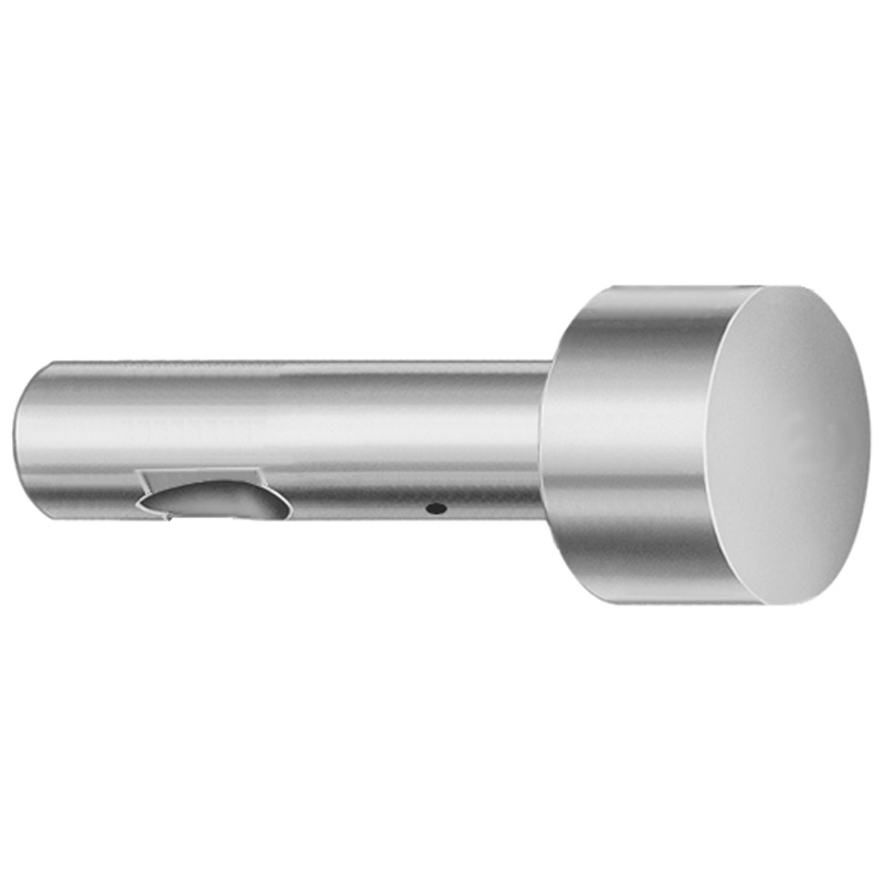
Point Larger than Shank Ball Lock Punches | Light Duty, Inch, CRN Coating
Point larger than shank ball lock punches (CRN coated) are designed for light-duty inch tooling, helping maintain reliable lock-up and consistent ejection performance in production molds. The larger point improves engagement where ejector access is constrained.
- Point larger than shank geometry supports stable ball lock engagement in inch molds
- CRN coating enhances surface wear resistance for longer punch life
- Controlled dimensional coding supports fit consistency with standard tooling assemblies
- Used in mold build-ups for light-duty ejection systems and related punch applications
Specifications
114 configurations available
| Tip Shape | D (Shank dia.) (in) | L (Length) (coded inch) | P Dimension (in) | W Dimension (in) | R Dimension (in) |
|---|---|---|---|---|---|
| H | 37 (0.3750") | 250 ~ 450 | 0.376 ~ 0.875 | 0.062 ~ 0.124 | - |
| H | 37 (0.3750") | 250 ~ 450 | 0.376 ~ 0.875 | 0.125 ~ 0.875 | - |
| H | 50 (0.5000") | 250 ~ 450 | 0.501 ~ 1.25 | 0.158 ~ 0.187 | - |
| H | 50 (0.5000") | 250 ~ 450 | 0.501 ~ 1.25 | 0.188 ~ 1.25 | - |
| H | 62 (0.6250") | 250 ~ 450 | 0.626 ~ 1.5 | 0.25 ~ 1.5 | - |
| H | 62 (0.6250") | 250 ~ 450 | 0.626 ~ 1.5 | 0.158 ~ 0.249 | - |
| H | 75 (0.7500") | 250 ~ 450 | 0.751 ~ 1.5 | 0.235 ~ 0.311 | - |
| H | 75 (0.7500") | 250 ~ 450 | 0.751 ~ 1.5 | 0.312 ~ 1.5 | - |
| H | 87 (0.8750") | 250 ~ 450 | 0.876 ~ 1.75 | 0.235 ~ 0.374 | - |
| H | 87 (0.8750") | 250 ~ 450 | 0.876 ~ 1.75 | 0.375 ~ 1.75 | - |
| H | 100 (1.0000") | 250 ~ 450 | 1.001 ~ 1.75 | 0.235 ~ 0.436 | - |
| H | 100 (1.0000") | 250 ~ 450 | 1.001 ~ 1.75 | 0.437 ~ 1.75 | - |
| J | 37 (0.3750") | 250 ~ 450 | 0.376 ~ 0.875 | 0.062 ~ 0.124 | - |
| J | 37 (0.3750") | 250 ~ 450 | 0.376 ~ 0.875 | 0.125 ~ 0.875 | - |
| J | 50 (0.5000") | 250 ~ 450 | 0.501 ~ 1.25 | 0.158 ~ 0.187 | - |
| J | 50 (0.5000") | 250 ~ 450 | 0.501 ~ 1.25 | 0.188 ~ 1.25 | - |
| J | 62 (0.6250") | 250 ~ 450 | 0.626 ~ 1.5 | 0.25 ~ 1.5 | - |
| J | 62 (0.6250") | 250 ~ 450 | 0.626 ~ 1.5 | 0.158 ~ 0.249 | - |
| J | 75 (0.7500") | 250 ~ 450 | 0.751 ~ 1.5 | 0.235 ~ 0.311 | - |
| J | 75 (0.7500") | 250 ~ 450 | 0.751 ~ 1.5 | 0.312 ~ 1.5 | - |
| J | 87 (0.8750") | 250 ~ 450 | 0.876 ~ 1.75 | 0.235 ~ 0.374 | - |
| J | 87 (0.8750") | 250 ~ 450 | 0.876 ~ 1.75 | 0.375 ~ 1.75 | - |
| J | 100 (1.0000") | 250 ~ 450 | 1.001 ~ 1.75 | 0.235 ~ 0.436 | - |
| J | 100 (1.0000") | 250 ~ 450 | 1.001 ~ 1.75 | 0.437 ~ 1.75 | - |
| K | 37 (0.3750") | 250 ~ 450 | 0.376 ~ 0.875 | 0.062 ~ 0.124 | 0.007 ~ 0.4375 |
| K | 37 (0.3750") | 250 ~ 450 | 0.376 ~ 0.875 | 0.125 ~ 0.875 | 0.007 ~ 0.4375 |
| K | 50 (0.5000") | 250 ~ 450 | 0.501 ~ 1.25 | 0.158 ~ 0.187 | 0.007 ~ 0.625 |
| K | 50 (0.5000") | 250 ~ 450 | 0.501 ~ 1.25 | 0.188 ~ 1.25 | 0.007 ~ 0.625 |
| K | 62 (0.6250") | 250 ~ 450 | 0.626 ~ 1.5 | 0.25 ~ 1.5 | 0.007 ~ 0.75 |
| K | 62 (0.6250") | 250 ~ 450 | 0.626 ~ 1.5 | 0.158 ~ 0.249 | 0.007 ~ 0.75 |
| K | 75 (0.7500") | 250 ~ 450 | 0.751 ~ 1.5 | 0.235 ~ 0.311 | 0.007 ~ 0.75 |
| K | 75 (0.7500") | 250 ~ 450 | 0.751 ~ 1.5 | 0.312 ~ 1.5 | 0.007 ~ 0.75 |
| K | 87 (0.8750") | 250 ~ 450 | 0.876 ~ 1.75 | 0.235 ~ 0.374 | 0.007 ~ 0.875 |
| K | 87 (0.8750") | 250 ~ 450 | 0.876 ~ 1.75 | 0.375 ~ 1.75 | 0.007 ~ 0.875 |
| K | 100 (1.0000") | 250 ~ 450 | 1.001 ~ 1.75 | 0.235 ~ 0.436 | 0.007 ~ 0.875 |
| K | 100 (1.0000") | 250 ~ 450 | 1.001 ~ 1.75 | 0.437 ~ 1.75 | 0.007 ~ 0.875 |
| L | 37 (0.3750") | 250 ~ 450 | 0.376 ~ 0.875 | 0.062 ~ 0.124 | - |
| L | 37 (0.3750") | 250 ~ 450 | 0.376 ~ 0.875 | 0.125 ~ 0.875 | - |
| L | 50 (0.5000") | 250 ~ 450 | 0.501 ~ 1.25 | 0.158 ~ 0.187 | - |
| L | 50 (0.5000") | 250 ~ 450 | 0.501 ~ 1.25 | 0.188 ~ 1.25 | - |
| L | 62 (0.6250") | 250 ~ 450 | 0.626 ~ 1.5 | 0.25 ~ 1.5 | - |
| L | 62 (0.6250") | 250 ~ 450 | 0.626 ~ 1.5 | 0.158 ~ 0.249 | - |
| L | 75 (0.7500") | 250 ~ 450 | 0.751 ~ 1.5 | 0.235 ~ 0.311 | - |
| L | 75 (0.7500") | 250 ~ 450 | 0.751 ~ 1.5 | 0.312 ~ 1.5 | - |
| L | 87 (0.8750") | 250 ~ 450 | 0.876 ~ 1.75 | 0.235 ~ 0.374 | - |
| L | 87 (0.8750") | 250 ~ 450 | 0.876 ~ 1.75 | 0.375 ~ 1.75 | - |
| L | 100 (1.0000") | 250 ~ 450 | 1.001 ~ 1.75 | 0.235 ~ 0.436 | - |
| L | 100 (1.0000") | 250 ~ 450 | 1.001 ~ 1.75 | 0.437 ~ 1.75 | - |
| N | 37 (0.3750") | 250 ~ 450 | - | 0.326 ~ 0.758 | - |
| N | 50 (0.5000") | 250 ~ 450 | - | 0.434 ~ 1.083 | - |
Product Guide
Application Scenarios+
These point-larger-than-shank ball lock punches are used in light-duty inch injection mold tooling where ejector access is limited and consistent ball lock engagement is critical. The larger point geometry helps maintain stable lock-up in the mating pocket, reducing the risk of partial seating that can lead to inconsistent ejection.
- Automotive and industrial connector molds (light-duty): Use when ejector assemblies require reliable actuation but the available access around the lock interface is constrained.
- Appliance and consumer product housings: Suitable for production environments that need repeatable alignment of the ball lock mechanism to support steady cycle-to-cycle ejection.
- General light-duty mold build-ups: The coded fit consistency supports assembly with standard tooling components, helping maintain predictable interface dimensions.
The CRN coating variant is particularly suited for applications where surface wear at the lock interface and point area impacts long-term ejection stability.
Material & Process Details+
The product is specified for light-duty inch molds with a CRN coating to improve surface performance during repeated sliding and contact. While the input data does not list a specific base steel grade or heat-treatment state (e.g., HRC level, quenched & tempered, nitriding), the CRN coating is intended to raise wear resistance at the high-contact point region.
- Wear resistance: Enhanced coating coverage on the point area helps resist abrasion and fretting during lock/unlock cycles.
- Toughness trade-off: Coatings typically improve wear without fundamentally changing bulk toughness; however, the base material toughness still governs resistance to chipping under impact loads.
- Manufacturing process (interface-focused): After forming the punch body and point geometry, the CRN coating is applied to support longer service life where ejection stability depends on maintaining surface condition.
If you require a specific steel grade/heat-treatment spec for your design, provide your target hardness and load profile for confirmation.
Sizing & Selection Guide+
Select the punch series by matching its variable geometry to your mold’s ball lock pocket and the ejector linkage interface. This variant is defined by an inch D (shank dia.) range of 0.3750–1.0000 in (37–100). Choose the L (coded inch length) from 250–450 to ensure full engagement length while maintaining clearance in the tool stack.
- Tip shape: Pick the coded tip shape H, J, K, L, N, O, R, V, X, Y, Z to correspond with your lock pocket contour and required engagement profile.
- Point/geometry dimensions: Match P within the available ranges (0.376–0.875, 0.501–1.25, 0.626–1.5, 0.751–1.5, 0.876–1.75, 1.001–1.75) and W within 0.062–0.867.
- Radius feature: Ensure R fits the lock pocket curvature using the provided ranges (0.007–0.4375, 0.007–0.625, 0.007–0.75, 0.007–0.875).
These dimensions are intended to maintain fit consistency with standard tooling assemblies. Since tolerance values are not provided in the input data, confirm your assembly drawing/standard before final lock-up verification.
Frequently Asked Questions
Which dimension controls ball lock engagement stability for this point-larger-than-shank punch?+
How do I choose the correct shank diameter D and length L for my mold stack?+
What does the CRN coating add for wear and ejection stability in light-duty molds?+
How do I select the right tip shape and radius R for a specific lock pocket contour?+
Are P, W, and R independently configurable, or tied to the chosen D and tip shape?+
Related Products


Need Custom Specifications?
Our engineering team can help with custom configurations, material selection, and volume pricing.