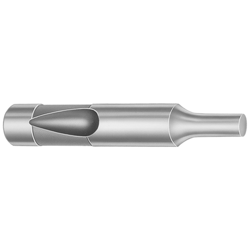
M2 Steel Ball Lock Regular Punches - Heavy Duty
Ball Lock Regular Punches - Heavy Duty (M2 steel) provide stable ball-lock retention for reliable part ejection in press tooling. The XCD coating supports wear resistance for sustained production.
- Heavy-duty ball lock design improves punch staying power in die assemblies
- M2 steel construction with XCD coating enhances abrasion resistance during runs
- Engineered for consistent fit across coded point length ranges for controlled build-up
- Used in die sets for blanking, forming, and general mechanical punch applications
Specifications
1950 configurations available
| Tip Shape | Material | D (Shank dia.) (in) | Standard Point Length & L (Length) (coded inch) | [B] Point Length B & L (Length) (coded inch) | [C] Point Length B & L (Length) (coded inch) | [D] Point Length B & L (Length) (coded inch) | P Dimension (in) | W Dimension (in) | R Dimension (in) |
|---|---|---|---|---|---|---|---|---|---|
| H | M2 | 37 (0.3750") | 250 ~ 600 | - | - | - | 0.05 ~ 0.374 | 0.05 ~ 0.124 | - |
| H | M2 | 37 (0.3750") | 250 ~ 600 | - | - | - | 0.05 ~ 0.374 | 0.062 ~ 0.374 | - |
| H | PS4 | 37 (0.3750") | 250 ~ 600 | - | - | - | 0.05 ~ 0.374 | 0.05 ~ 0.124 | - |
| H | PS4 | 37 (0.3750") | 250 ~ 600 | - | - | - | 0.05 ~ 0.374 | 0.062 ~ 0.374 | - |
| H | M2 | 37 (0.3750") | - | 250 ~ 600 | - | - | 0.05 ~ 0.374 | 0.05 ~ 0.124 | - |
| H | M2 | 37 (0.3750") | - | 250 ~ 600 | - | - | 0.05 ~ 0.374 | 0.062 ~ 0.374 | - |
| H | PS4 | 37 (0.3750") | - | 250 ~ 600 | - | - | 0.05 ~ 0.374 | 0.05 ~ 0.124 | - |
| H | PS4 | 37 (0.3750") | - | 250 ~ 600 | - | - | 0.05 ~ 0.374 | 0.062 ~ 0.374 | - |
| H | M2 | 37 (0.3750") | - | - | 250 ~ 600 | - | 0.05 ~ 0.374 | 0.05 ~ 0.124 | - |
| H | M2 | 37 (0.3750") | - | - | 250 ~ 600 | - | 0.05 ~ 0.374 | 0.062 ~ 0.374 | - |
| H | PS4 | 37 (0.3750") | - | - | 250 ~ 600 | - | 0.05 ~ 0.374 | 0.05 ~ 0.124 | - |
| H | PS4 | 37 (0.3750") | - | - | 250 ~ 600 | - | 0.05 ~ 0.374 | 0.062 ~ 0.374 | - |
| H | M2 | 50 (0.5000") | 250 ~ 700 | - | - | - | 0.093 ~ 0.186 | 0.093 ~ 0.186 | - |
| H | M2 | 50 (0.5000") | 250 ~ 700 | - | - | - | 0.093 ~ 0.186 | 0.187 ~ 0.499 | - |
| H | M2 | 50 (0.5000") | 250 ~ 700 | - | - | - | 0.187 ~ 0.499 | 0.093 ~ 0.186 | - |
| H | M2 | 50 (0.5000") | 250 ~ 700 | - | - | - | 0.187 ~ 0.499 | 0.187 ~ 0.499 | - |
| H | PS4 | 50 (0.5000") | 250 ~ 700 | - | - | - | 0.093 ~ 0.186 | 0.093 ~ 0.186 | - |
| H | PS4 | 50 (0.5000") | 250 ~ 700 | - | - | - | 0.093 ~ 0.186 | 0.187 ~ 0.499 | - |
| H | PS4 | 50 (0.5000") | 250 ~ 700 | - | - | - | 0.187 ~ 0.499 | 0.093 ~ 0.186 | - |
| H | PS4 | 50 (0.5000") | 250 ~ 700 | - | - | - | 0.187 ~ 0.499 | 0.187 ~ 0.499 | - |
| H | M2 | 50 (0.5000") | - | 250 ~ 700 | - | - | 0.093 ~ 0.186 | 0.093 ~ 0.186 | - |
| H | M2 | 50 (0.5000") | - | 250 ~ 700 | - | - | 0.093 ~ 0.186 | 0.187 ~ 0.499 | - |
| H | M2 | 50 (0.5000") | - | 250 ~ 700 | - | - | 0.187 ~ 0.499 | 0.093 ~ 0.186 | - |
| H | M2 | 50 (0.5000") | - | 250 ~ 700 | - | - | 0.187 ~ 0.499 | 0.187 ~ 0.499 | - |
| H | PS4 | 50 (0.5000") | - | 250 ~ 700 | - | - | 0.093 ~ 0.186 | 0.093 ~ 0.186 | - |
| H | PS4 | 50 (0.5000") | - | 250 ~ 700 | - | - | 0.093 ~ 0.186 | 0.187 ~ 0.499 | - |
| H | PS4 | 50 (0.5000") | - | 250 ~ 700 | - | - | 0.187 ~ 0.499 | 0.093 ~ 0.186 | - |
| H | PS4 | 50 (0.5000") | - | 250 ~ 700 | - | - | 0.187 ~ 0.499 | 0.187 ~ 0.499 | - |
| H | M2 | 50 (0.5000") | - | - | 250 ~ 700 | - | 0.093 ~ 0.186 | 0.093 ~ 0.186 | - |
| H | M2 | 50 (0.5000") | - | - | 250 ~ 700 | - | 0.093 ~ 0.186 | 0.187 ~ 0.499 | - |
| H | M2 | 50 (0.5000") | - | - | 250 ~ 700 | - | 0.187 ~ 0.499 | 0.093 ~ 0.186 | - |
| H | M2 | 50 (0.5000") | - | - | 250 ~ 700 | - | 0.187 ~ 0.499 | 0.187 ~ 0.499 | - |
| H | PS4 | 50 (0.5000") | - | - | 250 ~ 700 | - | 0.093 ~ 0.186 | 0.093 ~ 0.186 | - |
| H | PS4 | 50 (0.5000") | - | - | 250 ~ 700 | - | 0.093 ~ 0.186 | 0.187 ~ 0.499 | - |
| H | PS4 | 50 (0.5000") | - | - | 250 ~ 700 | - | 0.187 ~ 0.499 | 0.093 ~ 0.186 | - |
| H | PS4 | 50 (0.5000") | - | - | 250 ~ 700 | - | 0.187 ~ 0.499 | 0.187 ~ 0.499 | - |
| H | M2 | 50 (0.5000") | - | - | - | 275 ~ 700 | 0.093 ~ 0.186 | 0.093 ~ 0.186 | - |
| H | M2 | 50 (0.5000") | - | - | - | 275 ~ 700 | 0.093 ~ 0.186 | 0.187 ~ 0.499 | - |
| H | M2 | 50 (0.5000") | - | - | - | 275 ~ 700 | 0.187 ~ 0.499 | 0.093 ~ 0.186 | - |
| H | M2 | 50 (0.5000") | - | - | - | 275 ~ 700 | 0.187 ~ 0.499 | 0.187 ~ 0.499 | - |
| H | PS4 | 50 (0.5000") | - | - | - | 275 ~ 700 | 0.093 ~ 0.186 | 0.093 ~ 0.186 | - |
| H | PS4 | 50 (0.5000") | - | - | - | 275 ~ 700 | 0.093 ~ 0.186 | 0.187 ~ 0.499 | - |
| H | PS4 | 50 (0.5000") | - | - | - | 275 ~ 700 | 0.187 ~ 0.499 | 0.093 ~ 0.186 | - |
| H | PS4 | 50 (0.5000") | - | - | - | 275 ~ 700 | 0.187 ~ 0.499 | 0.187 ~ 0.499 | - |
| H | M2 | 62 (0.6250") | 250 ~ 700 | - | - | - | 0.25 ~ 0.624 | 0.25 ~ 0.624 | - |
| H | M2 | 62 (0.6250") | 250 ~ 700 | - | - | - | 0.25 ~ 0.624 | 0.125 ~ 0.249 | - |
| H | M2 | 62 (0.6250") | 250 ~ 700 | - | - | - | 0.125 ~ 0.249 | 0.25 ~ 0.624 | - |
| H | M2 | 62 (0.6250") | 250 ~ 700 | - | - | - | 0.125 ~ 0.249 | 0.125 ~ 0.249 | - |
| H | PS4 | 62 (0.6250") | 250 ~ 700 | - | - | - | 0.25 ~ 0.624 | 0.25 ~ 0.624 | - |
| H | PS4 | 62 (0.6250") | 250 ~ 700 | - | - | - | 0.25 ~ 0.624 | 0.125 ~ 0.249 | - |
Product Guide
Application Scenarios+
These heavy-duty ball-lock punches are used in injection- or press-assisted die sets where consistent ejection depends on stable punch retention. The ball-lock geometry improves staying power in the punch holder, reducing the risk of micro-movement that can disturb part ejection and shut height.
In automotive connector and bracket tooling, the variant with XCD coating helps resist abrasion during repeated blanking and forming cycles. This coating supports longer service intervals when the punch tip experiences frequent sliding/impact against workpiece material.
- Blanking and forming dies: reliable retention plus wear support for steady ejection across long production runs.
- Mechanical punch applications: suited where tool life is affected by edge wear and the need for repeatable assembly fit.
- Die assemblies with coded point lengths: chosen for controlled build-up and consistent alignment across the supported length codes.
Selection is especially practical when you need heavy-duty retention performance with the corrosion/wear advantages implied by the XCD coating on an M2 base.
Material & Process Details+
This product is available in M2 steel or PS4, with an XCD coating option described for efficient ejection. M2 is a high-speed steel known for strong wear resistance and adequate toughness for punch operations; it is typically quenched and tempered to reach service hardness, supporting stable cutting and punching performance under intermittent impact.
For wear-focused tooling, the XCD coating is intended to reduce abrasion at the punch tip during production, improving run-to-run consistency. The trade-off is that highly wear-optimized surfaces can be more sensitive to gross misalignment or excessive side loading, so proper build-up control matters.
- M2: best fit where cutting/punching wear dominates and toughness must remain sufficient for die use.
- PS4: an alternate material option when your die maker specifies a different base-property balance for the punch body.
Hardness (HRC), exact heat-treatment state, and comparative HRC values are not provided in the supplied specifications, so confirm the final heat-treatment/target HRC on the part drawing for your project.
Sizing & Selection Guide+
To select the correct ball-lock punch, match the shank diameter (D) and the coded point length to the die assembly requirements. The shank diameter range is 37 ~ 125 in, and the coded point length ranges are provided as multiple code sets: 250 ~ 600, 250 ~ 700, 275 ~ 700, and 300 ~ 700 (in coded inch).
Next, choose the required tip shape from H, J, K, L, N, O, R, V, X, Y, Z. Tip shape governs how the punch interacts with the workpiece edge and can affect ejection force distribution.
- Match D (shank dia.) to the punch holder bore/lock interface in your die set.
- Pick the correct L length code (e.g., 250~600 or 300~700) to control die build-up and punch protrusion.
- Consider P, W, R (P: 0.05~1, W: 0.05~0.5, R: 0.007~0.007) where your design references micro-geometry or retention-related features.
Tolerance and the exact fit class for the ball-lock interface are not included in the supplied data—verify against the drawing/spec sheet for your holder system before finalizing.
Frequently Asked Questions
Which material should I choose (M2 vs PS4) for heavy-duty ball-lock punch service with XCD coating?+
How do I select the correct coded point length L for punch protrusion and die build-up?+
What shank diameter D range is covered, and how does it relate to compatibility with ball-lock holders?+
How does tip shape selection (H, J, K, L, N, O, R, V, X, Y, Z) affect ejection performance?+
Are the micro-geometry parameters P, W, and R fixed or variable for this punch series?+
Related Products


Need Custom Specifications?
Our engineering team can help with custom configurations, material selection, and volume pricing.