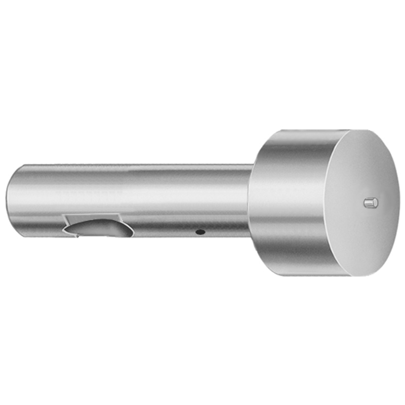
JIS Standard XCD Coating Dayton Point Larger than Shank Ball Lock Punches
Point larger than shank ball lock punches (Dayton) with XCD coating are designed for light-duty inch applications, helping eject parts reliably while maintaining positive lock contact inside the punch plate.
- Point larger than shank geometry improves engagement for consistent ejection force
- XCD coating supports wear resistance for longer service life in forming cycles
- Supports repeatable ball-lock alignment to reduce mis-seating during mold operation
- Used in tool-and-die build-ups for light-duty production runs
Specifications
114 configurations available
| Tip Shape | D (Shank dia.) (in) | Jektole group | L (Length) (coded inch) | P Dimension (in) | W Dimension (in) | R Dimension (in) |
|---|---|---|---|---|---|---|
| H | 37 (0.3750") | J4 | 250 ~ 450 | 0.376 ~ 0.875 | 0.062 ~ 0.124 | - |
| H | 37 (0.3750") | J4 | 250 ~ 450 | 0.376 ~ 0.875 | 0.125 ~ 0.875 | - |
| H | 50 (0.5000") | J6 | 250 ~ 450 | 0.501 ~ 1.25 | 0.158 ~ 0.187 | - |
| H | 50 (0.5000") | J6 | 250 ~ 450 | 0.501 ~ 1.25 | 0.188 ~ 1.25 | - |
| H | 62 (0.6250") | J6 | 250 ~ 450 | 0.626 ~ 1.5 | 0.25 ~ 1.5 | - |
| H | 62 (0.6250") | J6 | 250 ~ 450 | 0.626 ~ 1.5 | 0.158 ~ 0.249 | - |
| H | 75 (0.7500") | J9 | 250 ~ 450 | 0.751 ~ 1.5 | 0.235 ~ 0.311 | - |
| H | 75 (0.7500") | J9 | 250 ~ 450 | 0.751 ~ 1.5 | 0.312 ~ 1.5 | - |
| H | 87 (0.8750") | J9 | 250 ~ 450 | 0.876 ~ 1.75 | 0.235 ~ 0.374 | - |
| H | 87 (0.8750") | J9 | 250 ~ 450 | 0.876 ~ 1.75 | 0.375 ~ 1.75 | - |
| H | 100 (1.0000") | J9 | 250 ~ 450 | 1.001 ~ 1.75 | 0.235 ~ 0.436 | - |
| H | 100 (1.0000") | J9 | 250 ~ 450 | 1.001 ~ 1.75 | 0.437 ~ 1.75 | - |
| J | 37 (0.3750") | J4 | 250 ~ 450 | 0.376 ~ 0.875 | 0.062 ~ 0.124 | - |
| J | 37 (0.3750") | J4 | 250 ~ 450 | 0.376 ~ 0.875 | 0.125 ~ 0.875 | - |
| J | 50 (0.5000") | J6 | 250 ~ 450 | 0.501 ~ 1.25 | 0.158 ~ 0.187 | - |
| J | 50 (0.5000") | J6 | 250 ~ 450 | 0.501 ~ 1.25 | 0.188 ~ 1.25 | - |
| J | 62 (0.6250") | J6 | 250 ~ 450 | 0.626 ~ 1.5 | 0.25 ~ 1.5 | - |
| J | 62 (0.6250") | J6 | 250 ~ 450 | 0.626 ~ 1.5 | 0.158 ~ 0.249 | - |
| J | 75 (0.7500") | J9 | 250 ~ 450 | 0.751 ~ 1.5 | 0.235 ~ 0.311 | - |
| J | 75 (0.7500") | J9 | 250 ~ 450 | 0.751 ~ 1.5 | 0.312 ~ 1.5 | - |
| J | 87 (0.8750") | J9 | 250 ~ 450 | 0.876 ~ 1.75 | 0.235 ~ 0.374 | - |
| J | 87 (0.8750") | J9 | 250 ~ 450 | 0.876 ~ 1.75 | 0.375 ~ 1.75 | - |
| J | 100 (1.0000") | J9 | 250 ~ 450 | 1.001 ~ 1.75 | 0.235 ~ 0.436 | - |
| J | 100 (1.0000") | J9 | 250 ~ 450 | 1.001 ~ 1.75 | 0.437 ~ 1.75 | - |
| K | 37 (0.3750") | J4 | 250 ~ 450 | 0.376 ~ 0.875 | 0.062 ~ 0.124 | 0.007 ~ 0.4375 |
| K | 37 (0.3750") | J4 | 250 ~ 450 | 0.376 ~ 0.875 | 0.125 ~ 0.875 | 0.007 ~ 0.4375 |
| K | 50 (0.5000") | J6 | 250 ~ 450 | 0.501 ~ 1.25 | 0.158 ~ 0.187 | 0.007 ~ 0.625 |
| K | 50 (0.5000") | J6 | 250 ~ 450 | 0.501 ~ 1.25 | 0.188 ~ 1.25 | 0.007 ~ 0.625 |
| K | 62 (0.6250") | J6 | 250 ~ 450 | 0.626 ~ 1.5 | 0.25 ~ 1.5 | 0.007 ~ 0.75 |
| K | 62 (0.6250") | J6 | 250 ~ 450 | 0.626 ~ 1.5 | 0.158 ~ 0.249 | 0.007 ~ 0.75 |
| K | 75 (0.7500") | J9 | 250 ~ 450 | 0.751 ~ 1.5 | 0.235 ~ 0.311 | 0.007 ~ 0.75 |
| K | 75 (0.7500") | J9 | 250 ~ 450 | 0.751 ~ 1.5 | 0.312 ~ 1.5 | 0.007 ~ 0.75 |
| K | 87 (0.8750") | J9 | 250 ~ 450 | 0.876 ~ 1.75 | 0.235 ~ 0.374 | 0.007 ~ 0.875 |
| K | 87 (0.8750") | J9 | 250 ~ 450 | 0.876 ~ 1.75 | 0.375 ~ 1.75 | 0.007 ~ 0.875 |
| K | 100 (1.0000") | J9 | 250 ~ 450 | 1.001 ~ 1.75 | 0.235 ~ 0.436 | 0.007 ~ 0.875 |
| K | 100 (1.0000") | J9 | 250 ~ 450 | 1.001 ~ 1.75 | 0.437 ~ 1.75 | 0.007 ~ 0.875 |
| L | 37 (0.3750") | J4 | 250 ~ 450 | 0.376 ~ 0.875 | 0.062 ~ 0.124 | - |
| L | 37 (0.3750") | J4 | 250 ~ 450 | 0.376 ~ 0.875 | 0.125 ~ 0.875 | - |
| L | 50 (0.5000") | J6 | 250 ~ 450 | 0.501 ~ 1.25 | 0.158 ~ 0.187 | - |
| L | 50 (0.5000") | J6 | 250 ~ 450 | 0.501 ~ 1.25 | 0.188 ~ 1.25 | - |
| L | 62 (0.6250") | J6 | 250 ~ 450 | 0.626 ~ 1.5 | 0.25 ~ 1.5 | - |
| L | 62 (0.6250") | J6 | 250 ~ 450 | 0.626 ~ 1.5 | 0.158 ~ 0.249 | - |
| L | 75 (0.7500") | J9 | 250 ~ 450 | 0.751 ~ 1.5 | 0.235 ~ 0.311 | - |
| L | 75 (0.7500") | J9 | 250 ~ 450 | 0.751 ~ 1.5 | 0.312 ~ 1.5 | - |
| L | 87 (0.8750") | J9 | 250 ~ 450 | 0.876 ~ 1.75 | 0.235 ~ 0.374 | - |
| L | 87 (0.8750") | J9 | 250 ~ 450 | 0.876 ~ 1.75 | 0.375 ~ 1.75 | - |
| L | 100 (1.0000") | J9 | 250 ~ 450 | 1.001 ~ 1.75 | 0.235 ~ 0.436 | - |
| L | 100 (1.0000") | J9 | 250 ~ 450 | 1.001 ~ 1.75 | 0.437 ~ 1.75 | - |
| N | 37 (0.3750") | J4 | 250 ~ 450 | - | 0.326 ~ 0.758 | - |
| N | 50 (0.5000") | J6 | 250 ~ 450 | - | 0.434 ~ 1.083 | - |
Product Guide
Application Scenarios+
This Dayton point larger-than-shank ball lock punch is used in light-duty inch injection mold tooling where stable ball-lock engagement is required for reliable part ejection. The geometry increases engagement length versus the shank, improving how consistently the lock contacts the punch plate during cycling.
Automotive interior and trim components often benefit from this style when ejector loads are moderate and cycle-to-cycle repeatability matters. The larger point helps maintain consistent ejection force while reducing the risk of mis-seating during mold open/close.
Consumer goods and small appliance housings use ejector systems with compact space constraints; this variant’s inch-based shank diameter options (0.375–1.000 in) make it practical for tool-and-die build-ups. The XCD coating is suited for wear-prone operations, supporting longer service life under repeated ejection.
- Light-duty inch molds with ball-lock ejection
- Applications prioritizing stable alignment and consistent lock contact
- Wear-resistance needs addressed by XCD coating
Material & Process Details+
The provided datasheet specifies a JIS Standard XCD coating on the Dayton ball-lock punch tip for improved wear behavior in service. While the steel grade and exact heat treatment condition (e.g., quench & temper, nitriding) are not included in the input data, the XCD coating indicates a surface-engineered approach intended to resist wear at the lock/contact zone.
In ball-lock ejector components, the key trade-off is surface durability vs. core toughness: coatings typically enhance abrasion and fretting resistance where the punch and plate interfaces rub, while the underlying tool steel must remain tough enough to prevent chipping under repeated mechanical loading.
- XCD coating: targets wear resistance at the engagement and sliding surfaces
- Material grade/heat-treatment not specified in the input—confirm during engineering verification
If you need a coating-to-steel comparison for your production wear profile, supply the target load/cycle count and we can recommend an appropriate base material/heat treatment combination for the mold steel standard you use.
Sizing & Selection Guide+
Select this ball-lock punch by matching three dimensional groups: D (shank diameter), L (coded length 250–450), and the point-to-shank geometry defined by P, W, and R ranges. Because this is a “point larger than shank” design, the lock engagement depends on the point dimensions being compatible with the mating punch plate geometry.
- Choose D (in): 0.3750, 0.5000, 0.6250, 0.7500, 0.8750, or 1.0000
- Choose L (coded inch): 250 ~ 450
- Select tip shape: H, J, K, L, N, O, R, V, X, Y, Z to match your ejector layout
Then verify that your cavity/core and punch plate clearances allow the selected P (0.376–0.875, 0.501–1.25, 0.626–1.5, 0.751–1.5, 0.876–1.75, 1.001–1.75 in), W (0.062–0.867 in), and R (0.007–0.4375, 0.007–0.625, 0.007–0.75, 0.007–0.875 in). Keep in mind that ball-lock alignment is sensitive to fit; confirm functional clearances for the Jektole group (J4, J6, J9) and your plate tolerances to avoid mis-seating.
Frequently Asked Questions
Which shank diameter options (D) are available for this Dayton larger-than-shank ball lock punch?+
The available D (shank diameter) options are 0.3750 in, 0.5000 in, 0.6250 in, 0.7500 in, 0.8750 in, and 1.0000 in (37, 50, 62, 75, 87, 100 in thousandths). Select the diameter that matches the punch plate bore and ejector system dimensional standard used in your inch mold.
How do I choose the correct length for ball-lock punch placement—what does the coded L range mean?+
This product lists L (coded inch) as 250 ~ 450. When specifying, match the coded length to your tool stack-up and required stroke for the ejector return path, ensuring the ball-lock engagement area stays within the punch plate guide zone.
What tip shape and Jektole group combinations are supported for this series?+
The tip shape is variable: H, J, K, L, N, O, R, V, X, Y, Z. The Jektole group is available as J4, J6, J9; use the same group as your mating ball-lock punch plate standard to maintain correct alignment and lock contact.
What dimensional ranges should I verify for the point larger-than-shank geometry (P, W, R)?+
Verify compatibility of the engagement geometry by checking P (0.376–0.875, 0.501–1.25, 0.626–1.5, 0.751–1.5, 0.876–1.75, 1.001–1.75 in), W (0.062–0.867 in), and R (0.007–0.4375, 0.007–0.625, 0.007–0.75, 0.007–0.875 in). These ranges govern how the larger point engages the punch plate, so mismatch can cause mis-seating.
What does the XCD coating imply for wear resistance in ball-lock ejector service?+
The series specifies a JIS Standard XCD coating, intended to improve wear resistance at the contact and sliding surfaces involved in ball-lock ejection. This helps support longer service life under repeated ejection cycles, particularly in light-duty inch molds where wear and fretting at engagement points can accumulate.
Related Products


Need Custom Specifications?
Our engineering team can help with custom configurations, material selection, and volume pricing.