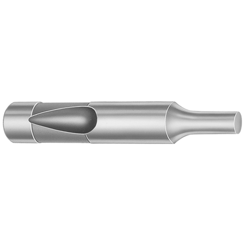
Ball Lock Regular Punches - Heavy Duty, Inch (XN DayTride® Coating)
Ball Lock Regular Punches - Heavy Duty, Inch (XN DayTride® Coating) deliver stable ball-lock retention for repeatable part ejection in demanding die sets. Select the tip geometry and punch blank configuration that matches your tool layout and production load.
- Ball-lock punch head design supports consistent positioning and ejector performance
- Engineered materials options for wear resistance and reliable long-cycle operation
- Tip shape selection (X, R, K, O, H, L, J, N, V, Y, Z) for matching die requirements
- Coated finish improves surface durability for punch-and-die release applications
Specifications
1950 configurations available
| Tip Shape | Material | D (Shank dia.) (in) | Standard Point Length & L (Length) (coded inch) | [B] Point Length B & L (Length) (coded inch) | [C] Point Length B & L (Length) (coded inch) | [D] Point Length B & L (Length) (coded inch) | P Dimension (in) | W Dimension (in) | R Dimension (in) |
|---|---|---|---|---|---|---|---|---|---|
| H | M2 | 37 (0.3750") | 250 ~ 600 | - | - | - | 0.05 ~ 0.374 | 0.05 ~ 0.124 | - |
| H | M2 | 37 (0.3750") | 250 ~ 600 | - | - | - | 0.05 ~ 0.374 | 0.062 ~ 0.374 | - |
| H | PS4 | 37 (0.3750") | 250 ~ 600 | - | - | - | 0.05 ~ 0.374 | 0.05 ~ 0.124 | - |
| H | PS4 | 37 (0.3750") | 250 ~ 600 | - | - | - | 0.05 ~ 0.374 | 0.062 ~ 0.374 | - |
| H | M2 | 37 (0.3750") | - | 250 ~ 600 | - | - | 0.05 ~ 0.374 | 0.05 ~ 0.124 | - |
| H | M2 | 37 (0.3750") | - | 250 ~ 600 | - | - | 0.05 ~ 0.374 | 0.062 ~ 0.374 | - |
| H | PS4 | 37 (0.3750") | - | 250 ~ 600 | - | - | 0.05 ~ 0.374 | 0.05 ~ 0.124 | - |
| H | PS4 | 37 (0.3750") | - | 250 ~ 600 | - | - | 0.05 ~ 0.374 | 0.062 ~ 0.374 | - |
| H | M2 | 37 (0.3750") | - | - | 250 ~ 600 | - | 0.05 ~ 0.374 | 0.05 ~ 0.124 | - |
| H | M2 | 37 (0.3750") | - | - | 250 ~ 600 | - | 0.05 ~ 0.374 | 0.062 ~ 0.374 | - |
| H | PS4 | 37 (0.3750") | - | - | 250 ~ 600 | - | 0.05 ~ 0.374 | 0.05 ~ 0.124 | - |
| H | PS4 | 37 (0.3750") | - | - | 250 ~ 600 | - | 0.05 ~ 0.374 | 0.062 ~ 0.374 | - |
| H | M2 | 50 (0.5000") | 250 ~ 700 | - | - | - | 0.093 ~ 0.186 | 0.093 ~ 0.186 | - |
| H | M2 | 50 (0.5000") | 250 ~ 700 | - | - | - | 0.093 ~ 0.186 | 0.187 ~ 0.499 | - |
| H | M2 | 50 (0.5000") | 250 ~ 700 | - | - | - | 0.187 ~ 0.499 | 0.093 ~ 0.186 | - |
| H | M2 | 50 (0.5000") | 250 ~ 700 | - | - | - | 0.187 ~ 0.499 | 0.187 ~ 0.499 | - |
| H | PS4 | 50 (0.5000") | 250 ~ 700 | - | - | - | 0.093 ~ 0.186 | 0.093 ~ 0.186 | - |
| H | PS4 | 50 (0.5000") | 250 ~ 700 | - | - | - | 0.093 ~ 0.186 | 0.187 ~ 0.499 | - |
| H | PS4 | 50 (0.5000") | 250 ~ 700 | - | - | - | 0.187 ~ 0.499 | 0.093 ~ 0.186 | - |
| H | PS4 | 50 (0.5000") | 250 ~ 700 | - | - | - | 0.187 ~ 0.499 | 0.187 ~ 0.499 | - |
| H | M2 | 50 (0.5000") | - | 250 ~ 700 | - | - | 0.093 ~ 0.186 | 0.093 ~ 0.186 | - |
| H | M2 | 50 (0.5000") | - | 250 ~ 700 | - | - | 0.093 ~ 0.186 | 0.187 ~ 0.499 | - |
| H | M2 | 50 (0.5000") | - | 250 ~ 700 | - | - | 0.187 ~ 0.499 | 0.093 ~ 0.186 | - |
| H | M2 | 50 (0.5000") | - | 250 ~ 700 | - | - | 0.187 ~ 0.499 | 0.187 ~ 0.499 | - |
| H | PS4 | 50 (0.5000") | - | 250 ~ 700 | - | - | 0.093 ~ 0.186 | 0.093 ~ 0.186 | - |
| H | PS4 | 50 (0.5000") | - | 250 ~ 700 | - | - | 0.093 ~ 0.186 | 0.187 ~ 0.499 | - |
| H | PS4 | 50 (0.5000") | - | 250 ~ 700 | - | - | 0.187 ~ 0.499 | 0.093 ~ 0.186 | - |
| H | PS4 | 50 (0.5000") | - | 250 ~ 700 | - | - | 0.187 ~ 0.499 | 0.187 ~ 0.499 | - |
| H | M2 | 50 (0.5000") | - | - | 250 ~ 700 | - | 0.093 ~ 0.186 | 0.093 ~ 0.186 | - |
| H | M2 | 50 (0.5000") | - | - | 250 ~ 700 | - | 0.093 ~ 0.186 | 0.187 ~ 0.499 | - |
| H | M2 | 50 (0.5000") | - | - | 250 ~ 700 | - | 0.187 ~ 0.499 | 0.093 ~ 0.186 | - |
| H | M2 | 50 (0.5000") | - | - | 250 ~ 700 | - | 0.187 ~ 0.499 | 0.187 ~ 0.499 | - |
| H | PS4 | 50 (0.5000") | - | - | 250 ~ 700 | - | 0.093 ~ 0.186 | 0.093 ~ 0.186 | - |
| H | PS4 | 50 (0.5000") | - | - | 250 ~ 700 | - | 0.093 ~ 0.186 | 0.187 ~ 0.499 | - |
| H | PS4 | 50 (0.5000") | - | - | 250 ~ 700 | - | 0.187 ~ 0.499 | 0.093 ~ 0.186 | - |
| H | PS4 | 50 (0.5000") | - | - | 250 ~ 700 | - | 0.187 ~ 0.499 | 0.187 ~ 0.499 | - |
| H | M2 | 50 (0.5000") | - | - | - | 275 ~ 700 | 0.093 ~ 0.186 | 0.093 ~ 0.186 | - |
| H | M2 | 50 (0.5000") | - | - | - | 275 ~ 700 | 0.093 ~ 0.186 | 0.187 ~ 0.499 | - |
| H | M2 | 50 (0.5000") | - | - | - | 275 ~ 700 | 0.187 ~ 0.499 | 0.093 ~ 0.186 | - |
| H | M2 | 50 (0.5000") | - | - | - | 275 ~ 700 | 0.187 ~ 0.499 | 0.187 ~ 0.499 | - |
| H | PS4 | 50 (0.5000") | - | - | - | 275 ~ 700 | 0.093 ~ 0.186 | 0.093 ~ 0.186 | - |
| H | PS4 | 50 (0.5000") | - | - | - | 275 ~ 700 | 0.093 ~ 0.186 | 0.187 ~ 0.499 | - |
| H | PS4 | 50 (0.5000") | - | - | - | 275 ~ 700 | 0.187 ~ 0.499 | 0.093 ~ 0.186 | - |
| H | PS4 | 50 (0.5000") | - | - | - | 275 ~ 700 | 0.187 ~ 0.499 | 0.187 ~ 0.499 | - |
| H | M2 | 62 (0.6250") | 250 ~ 700 | - | - | - | 0.25 ~ 0.624 | 0.25 ~ 0.624 | - |
| H | M2 | 62 (0.6250") | 250 ~ 700 | - | - | - | 0.25 ~ 0.624 | 0.125 ~ 0.249 | - |
| H | M2 | 62 (0.6250") | 250 ~ 700 | - | - | - | 0.125 ~ 0.249 | 0.25 ~ 0.624 | - |
| H | M2 | 62 (0.6250") | 250 ~ 700 | - | - | - | 0.125 ~ 0.249 | 0.125 ~ 0.249 | - |
| H | PS4 | 62 (0.6250") | 250 ~ 700 | - | - | - | 0.25 ~ 0.624 | 0.25 ~ 0.624 | - |
| H | PS4 | 62 (0.6250") | 250 ~ 700 | - | - | - | 0.25 ~ 0.624 | 0.125 ~ 0.249 | - |
Product Guide
Application Scenarios+
These heavy-duty ball-lock regular punches are designed for reliable ejection and stable retention inside injection or die tooling where repeatability and long service life matter.
- Automotive connector and terminal molds: Use the ball-lock head to maintain consistent positioning during repeated ejection cycles. The XN DayTride® coating supports durable punch-and-die release when running wear-prone alloys or textured cavity surfaces.
- Consumer and appliance housing inserts: Select an appropriate tip shape (X, R, K, O, H, L, J, N, V, Y, Z) to match cavity geometry and flow-related ejector access. The heavy-duty build helps sustain ejection performance in high-volume production.
- Industrial brackets and mounting features: Choose a punch blank size that fits the tool layout and production load. The available material options support wear resistance needs for repeated part ejection without losing retention stability.
By matching tip geometry and blank configuration to the die layout, you reduce ejection inconsistency and improve part release durability.
Material & Process Details+
This product is offered in M2 and PS4 material options, enabling trade-offs between wear resistance, toughness, and durability for ejector use.
- M2: A high-speed steel option commonly selected for strong abrasion and wear resistance under long-cycle punching/ejector conditions. It is typically heat-treated to a hardened state (commonly quenched and tempered) to balance hardness with toughness; the exact hardness depends on the supplier’s process.
- PS4: A tool-steel option aimed at reliable performance in punch-and-die release applications, with heat treatment tuned for dimensional stability and service life. It may offer a different toughness/wear balance compared with M2.
The XN DayTride® coating further improves surface durability for die release, helping reduce friction and wear at the punch face and shank areas.
Sizing & Selection Guide+
To select the correct ball-lock regular punch for your mold, start with the shank diameter (D) and the point/overall length code you need for the cavity/core interface.
- Choose D (shank dia.) within 37 ~ 125 in.
- Select length L (coded inch) from the available ranges: 250 ~ 600, 250 ~ 700, 275 ~ 700, or 300 ~ 700. Depending on configuration, you may also see 300 ~ 700 and narrower options.
- Confirm point length variants: the data lists point length B & L and point length C & L with the same coded ranges, plus a configuration that shows D point length B & L: 275 ~ 700 and 300 ~ 700.
Match tip shape (H, J, K, L, N, O, R, V, X, Y, Z) to your ejector knock-out geometry to ensure consistent clearance and engagement. When designing recesses or ejector pockets, allow for coating and practical fit; verify tool drawings for the specific fit/tolerance standard used on your assembly.
Frequently Asked Questions
Which tip shape options are available for ball-lock regular punches in this series?+
This series provides selectable tip shapes: H, J, K, L, N, O, R, V, X, Y, Z. Choose the tip geometry that matches your die knockout surface and desired ejector contact pattern.
What shank diameter and length code ranges can I order for these punches?+
The shank diameter (D) range is 37 ~ 125 in. The standard point length & L (coded inch) options are 250 ~ 600, 250 ~ 700, 275 ~ 700, and 300 ~ 700 (with corresponding B/L and C/L listings by configuration).
How do material options (M2 vs PS4) affect die release and wear for ejector punches?+
Material is available in M2 and PS4. For ejector applications with abrasion and long-cycle wear needs, M2 is typically selected for its strong wear characteristics after heat treatment; PS4 is selected for a different performance balance while maintaining punch-and-die release reliability.
What does the XN DayTride® coating contribute in ball-lock punch-and-die release use?+
The XN DayTride® coating is specified to improve surface durability for punch-and-die release. In practice, it helps reduce wear and frictional effects at the punch surface during repeated ejection cycles.
How should I match the punch length (L) to my mold cavity/core layout?+
Select L from the coded ranges (for example 250 ~ 600 or 300 ~ 700) so the punch point reaches the required ejection depth. Verify which configuration corresponds to the listed B & L or C & L point-length variants, and confirm the required pocket depth/clearance in your ejector plate design.
Related Products


Need Custom Specifications?
Our engineering team can help with custom configurations, material selection, and volume pricing.