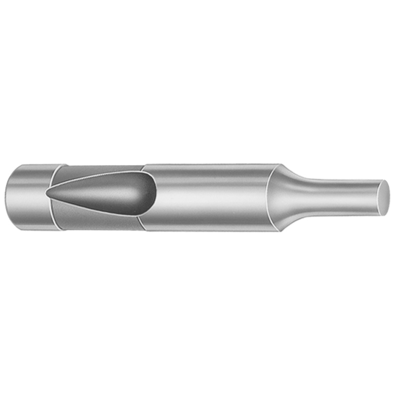
Inch Ball Lock Regular Punches Heavy Duty X-Shaped Tip
Ball lock regular punches heavy duty (inch) with an X-shaped tip are designed for stable positioning and consistent ejection in progressive or die operations. The selected punch geometry helps control contact with the workpiece while supporting repeatable press cycle performance.
- X-shaped tip provides controlled penetration for reliable ejector action
- Manufactured from M2 steel or PS4 for wear-resistant, long service life
- Coded point length/length options support assembly compatibility across die standards
- Suitable for heavy-duty tooling and punch systems where repeatability matters
Specifications
1950 configurations available
| Tip Shape | Material | D (Shank dia.) (in) | Standard Point Length & L (Length) (coded inch) | [B] Point Length B & L (Length) (coded inch) | [C] Point Length B & L (Length) (coded inch) | [D] Point Length B & L (Length) (coded inch) | P Dimension (in) | W Dimension (in) | R Dimension (in) |
|---|---|---|---|---|---|---|---|---|---|
| H | M2 | 37 (0.3750") | 250 ~ 600 | - | - | - | 0.05 ~ 0.374 | 0.05 ~ 0.124 | - |
| H | M2 | 37 (0.3750") | 250 ~ 600 | - | - | - | 0.05 ~ 0.374 | 0.062 ~ 0.374 | - |
| H | PS4 | 37 (0.3750") | 250 ~ 600 | - | - | - | 0.05 ~ 0.374 | 0.05 ~ 0.124 | - |
| H | PS4 | 37 (0.3750") | 250 ~ 600 | - | - | - | 0.05 ~ 0.374 | 0.062 ~ 0.374 | - |
| H | M2 | 37 (0.3750") | - | 250 ~ 600 | - | - | 0.05 ~ 0.374 | 0.05 ~ 0.124 | - |
| H | M2 | 37 (0.3750") | - | 250 ~ 600 | - | - | 0.05 ~ 0.374 | 0.062 ~ 0.374 | - |
| H | PS4 | 37 (0.3750") | - | 250 ~ 600 | - | - | 0.05 ~ 0.374 | 0.05 ~ 0.124 | - |
| H | PS4 | 37 (0.3750") | - | 250 ~ 600 | - | - | 0.05 ~ 0.374 | 0.062 ~ 0.374 | - |
| H | M2 | 37 (0.3750") | - | - | 250 ~ 600 | - | 0.05 ~ 0.374 | 0.05 ~ 0.124 | - |
| H | M2 | 37 (0.3750") | - | - | 250 ~ 600 | - | 0.05 ~ 0.374 | 0.062 ~ 0.374 | - |
| H | PS4 | 37 (0.3750") | - | - | 250 ~ 600 | - | 0.05 ~ 0.374 | 0.05 ~ 0.124 | - |
| H | PS4 | 37 (0.3750") | - | - | 250 ~ 600 | - | 0.05 ~ 0.374 | 0.062 ~ 0.374 | - |
| H | M2 | 50 (0.5000") | 250 ~ 700 | - | - | - | 0.093 ~ 0.186 | 0.093 ~ 0.186 | - |
| H | M2 | 50 (0.5000") | 250 ~ 700 | - | - | - | 0.093 ~ 0.186 | 0.187 ~ 0.499 | - |
| H | M2 | 50 (0.5000") | 250 ~ 700 | - | - | - | 0.187 ~ 0.499 | 0.093 ~ 0.186 | - |
| H | M2 | 50 (0.5000") | 250 ~ 700 | - | - | - | 0.187 ~ 0.499 | 0.187 ~ 0.499 | - |
| H | PS4 | 50 (0.5000") | 250 ~ 700 | - | - | - | 0.093 ~ 0.186 | 0.093 ~ 0.186 | - |
| H | PS4 | 50 (0.5000") | 250 ~ 700 | - | - | - | 0.093 ~ 0.186 | 0.187 ~ 0.499 | - |
| H | PS4 | 50 (0.5000") | 250 ~ 700 | - | - | - | 0.187 ~ 0.499 | 0.093 ~ 0.186 | - |
| H | PS4 | 50 (0.5000") | 250 ~ 700 | - | - | - | 0.187 ~ 0.499 | 0.187 ~ 0.499 | - |
| H | M2 | 50 (0.5000") | - | 250 ~ 700 | - | - | 0.093 ~ 0.186 | 0.093 ~ 0.186 | - |
| H | M2 | 50 (0.5000") | - | 250 ~ 700 | - | - | 0.093 ~ 0.186 | 0.187 ~ 0.499 | - |
| H | M2 | 50 (0.5000") | - | 250 ~ 700 | - | - | 0.187 ~ 0.499 | 0.093 ~ 0.186 | - |
| H | M2 | 50 (0.5000") | - | 250 ~ 700 | - | - | 0.187 ~ 0.499 | 0.187 ~ 0.499 | - |
| H | PS4 | 50 (0.5000") | - | 250 ~ 700 | - | - | 0.093 ~ 0.186 | 0.093 ~ 0.186 | - |
| H | PS4 | 50 (0.5000") | - | 250 ~ 700 | - | - | 0.093 ~ 0.186 | 0.187 ~ 0.499 | - |
| H | PS4 | 50 (0.5000") | - | 250 ~ 700 | - | - | 0.187 ~ 0.499 | 0.093 ~ 0.186 | - |
| H | PS4 | 50 (0.5000") | - | 250 ~ 700 | - | - | 0.187 ~ 0.499 | 0.187 ~ 0.499 | - |
| H | M2 | 50 (0.5000") | - | - | 250 ~ 700 | - | 0.093 ~ 0.186 | 0.093 ~ 0.186 | - |
| H | M2 | 50 (0.5000") | - | - | 250 ~ 700 | - | 0.093 ~ 0.186 | 0.187 ~ 0.499 | - |
| H | M2 | 50 (0.5000") | - | - | 250 ~ 700 | - | 0.187 ~ 0.499 | 0.093 ~ 0.186 | - |
| H | M2 | 50 (0.5000") | - | - | 250 ~ 700 | - | 0.187 ~ 0.499 | 0.187 ~ 0.499 | - |
| H | PS4 | 50 (0.5000") | - | - | 250 ~ 700 | - | 0.093 ~ 0.186 | 0.093 ~ 0.186 | - |
| H | PS4 | 50 (0.5000") | - | - | 250 ~ 700 | - | 0.093 ~ 0.186 | 0.187 ~ 0.499 | - |
| H | PS4 | 50 (0.5000") | - | - | 250 ~ 700 | - | 0.187 ~ 0.499 | 0.093 ~ 0.186 | - |
| H | PS4 | 50 (0.5000") | - | - | 250 ~ 700 | - | 0.187 ~ 0.499 | 0.187 ~ 0.499 | - |
| H | M2 | 50 (0.5000") | - | - | - | 275 ~ 700 | 0.093 ~ 0.186 | 0.093 ~ 0.186 | - |
| H | M2 | 50 (0.5000") | - | - | - | 275 ~ 700 | 0.093 ~ 0.186 | 0.187 ~ 0.499 | - |
| H | M2 | 50 (0.5000") | - | - | - | 275 ~ 700 | 0.187 ~ 0.499 | 0.093 ~ 0.186 | - |
| H | M2 | 50 (0.5000") | - | - | - | 275 ~ 700 | 0.187 ~ 0.499 | 0.187 ~ 0.499 | - |
| H | PS4 | 50 (0.5000") | - | - | - | 275 ~ 700 | 0.093 ~ 0.186 | 0.093 ~ 0.186 | - |
| H | PS4 | 50 (0.5000") | - | - | - | 275 ~ 700 | 0.093 ~ 0.186 | 0.187 ~ 0.499 | - |
| H | PS4 | 50 (0.5000") | - | - | - | 275 ~ 700 | 0.187 ~ 0.499 | 0.093 ~ 0.186 | - |
| H | PS4 | 50 (0.5000") | - | - | - | 275 ~ 700 | 0.187 ~ 0.499 | 0.187 ~ 0.499 | - |
| H | M2 | 62 (0.6250") | 250 ~ 700 | - | - | - | 0.25 ~ 0.624 | 0.25 ~ 0.624 | - |
| H | M2 | 62 (0.6250") | 250 ~ 700 | - | - | - | 0.25 ~ 0.624 | 0.125 ~ 0.249 | - |
| H | M2 | 62 (0.6250") | 250 ~ 700 | - | - | - | 0.125 ~ 0.249 | 0.25 ~ 0.624 | - |
| H | M2 | 62 (0.6250") | 250 ~ 700 | - | - | - | 0.125 ~ 0.249 | 0.125 ~ 0.249 | - |
| H | PS4 | 62 (0.6250") | 250 ~ 700 | - | - | - | 0.25 ~ 0.624 | 0.25 ~ 0.624 | - |
| H | PS4 | 62 (0.6250") | 250 ~ 700 | - | - | - | 0.25 ~ 0.624 | 0.125 ~ 0.249 | - |
Product Guide
Application Scenarios+
These heavy-duty ball lock punches with an X-shaped tip are used in industrial injection mold tooling and progressive die/ejector systems where stable contact and repeatable ejection are critical. The X-patterned tip geometry helps control penetration and improves ejector consistency when parts require precise knock-out without damaging thin walls.
- Automotive connector and bracket inserts: Ideal for ejector/punch stations that must cycle rapidly. The heavy-duty build and wear-resistant steel variants support long run times under abrasive material flow and repeated impacts.
- Appliance and housing components: Suitable for molds that eject over complex part contours. The controlled tip action reduces risk of uneven ejection and helps maintain consistent press-cycle performance.
- Electronics housings with fine features: Works well when punch tip behavior must be consistent across assemblies. Select this variant for reliable part ejection while maintaining tooling stability during frequent operation.
Choose the M2 or PS4 option to match your expected wear and toughness needs for your specific molding material and cycle rate.
Material & Process Details+
This series is offered in M2 or PS4 hardened steels, both selected for durability in ball lock punch and ejector applications. Both grades are intended to deliver high wear resistance for long service life during repeated punching and ejection cycles.
- M2 steel: Commonly chosen for elevated hardness and abrasion resistance. It offers a strong wear/toughness balance, but may require careful heat treatment control to avoid excessive brittleness under heavy shock loading.
- PS4 steel: Selected for robustness in tooling where consistent impact resistance is important. Compared with higher-speed variants, it may provide a different toughness-to-wear trade-off depending on the final hardness target.
Regardless of grade, production typically uses a hardened state (quenched and tempered for tool steels; nitriding may be applied depending on the shop/process) to achieve stable hardness and reduce surface wear. For final performance, confirm your required hardness in the HRC range with the supplier/manufacturer documentation for the chosen steel and heat treatment route.
Sizing & Selection Guide+
Selection starts with matching your mold/ejector station requirements to the punch shank diameter (D) and the configured tip/length codes. This series provides D (in) ranges of 37 ~ 125, so choose the shank size that fits your guide/bushing and ensures proper alignment in the ejector assembly.
- Tip shape: Pick the required tip shape (H, J, K, L, N, O, R, V, X, Y, Z) to match target ejection behavior and contact geometry.
- Point length and overall length: Configure from coded inch length sets such as 250 ~ 600, 250 ~ 700, 275 ~ 700, or 300 ~ 700, depending on which dimension set is listed for your target part.
- Ball lock fit: Ensure the selected P (0.05 ~ 1 in), W (0.05 ~ 0.5 in), and R (0.007 in) match the mating ball-lock groove/bearing features so the lock engages correctly without binding.
Use the coded length/point length options to align with cavity/core stack-up and assembly compatibility across die standards, and verify functional clearance and tolerance requirements for the ejector travel path.
Frequently Asked Questions
Which tip shapes are best suited for consistent ejection with an X-shaped tip geometry?+
How do I choose between M2 and PS4 steel for ball lock punches in high-cycle molding or die operations?+
What shank diameter (D) range should I select to match my ejector guide or support hardware?+
How do I match coded point length (B) and overall length (L) to my cavity/core stack-up?+
What are the key ball-lock interface dimensions (P, W, R) I must verify for proper locking?+
Related Products


Need Custom Specifications?
Our engineering team can help with custom configurations, material selection, and volume pricing.