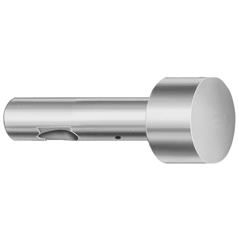
Ball Lock Ejector Punches Light Duty Inch X-Shaped Tip
Ball Lock Ejector Punches Light Duty Inch X-shaped tip are designed for stable ball-lock operation in injection or compression tooling. The X-shaped point helps control contact geometry for repeatable ejection performance.
- Ball-lock ejector punch design for dependable retention and alignment
- X-shaped tip geometry supports consistent contact during ejection
- Precision-ground construction for reliable assembly fit in dies
- Ideal for light-duty molding applications where smooth ejection is critical
Specifications
114 configurations available
| Tip Shape | D (Shank dia.) (in) | L (Length) (coded inch) | P Dimension (in) | W Dimension (in) | R Dimension (in) |
|---|---|---|---|---|---|
| H | 37 (0.3750") | 250 ~ 450 | 0.376 ~ 0.875 | 0.062 ~ 0.124 | - |
| H | 37 (0.3750") | 250 ~ 450 | 0.376 ~ 0.875 | 0.125 ~ 0.875 | - |
| H | 50 (0.5000") | 250 ~ 450 | 0.501 ~ 1.25 | 0.158 ~ 0.187 | - |
| H | 50 (0.5000") | 250 ~ 450 | 0.501 ~ 1.25 | 0.188 ~ 1.25 | - |
| H | 62 (0.6250") | 250 ~ 450 | 0.626 ~ 1.5 | 0.25 ~ 1.5 | - |
| H | 62 (0.6250") | 250 ~ 450 | 0.626 ~ 1.5 | 0.158 ~ 0.249 | - |
| H | 75 (0.7500") | 250 ~ 450 | 0.751 ~ 1.5 | 0.235 ~ 0.311 | - |
| H | 75 (0.7500") | 250 ~ 450 | 0.751 ~ 1.5 | 0.312 ~ 1.5 | - |
| H | 87 (0.8750") | 250 ~ 450 | 0.876 ~ 1.75 | 0.235 ~ 0.374 | - |
| H | 87 (0.8750") | 250 ~ 450 | 0.876 ~ 1.75 | 0.375 ~ 1.75 | - |
| H | 100 (1.0000") | 250 ~ 450 | 1.001 ~ 1.75 | 0.235 ~ 0.436 | - |
| H | 100 (1.0000") | 250 ~ 450 | 1.001 ~ 1.75 | 0.437 ~ 1.75 | - |
| J | 37 (0.3750") | 250 ~ 450 | 0.376 ~ 0.875 | 0.062 ~ 0.124 | - |
| J | 37 (0.3750") | 250 ~ 450 | 0.376 ~ 0.875 | 0.125 ~ 0.875 | - |
| J | 50 (0.5000") | 250 ~ 450 | 0.501 ~ 1.25 | 0.158 ~ 0.187 | - |
| J | 50 (0.5000") | 250 ~ 450 | 0.501 ~ 1.25 | 0.188 ~ 1.25 | - |
| J | 62 (0.6250") | 250 ~ 450 | 0.626 ~ 1.5 | 0.25 ~ 1.5 | - |
| J | 62 (0.6250") | 250 ~ 450 | 0.626 ~ 1.5 | 0.158 ~ 0.249 | - |
| J | 75 (0.7500") | 250 ~ 450 | 0.751 ~ 1.5 | 0.235 ~ 0.311 | - |
| J | 75 (0.7500") | 250 ~ 450 | 0.751 ~ 1.5 | 0.312 ~ 1.5 | - |
| J | 87 (0.8750") | 250 ~ 450 | 0.876 ~ 1.75 | 0.235 ~ 0.374 | - |
| J | 87 (0.8750") | 250 ~ 450 | 0.876 ~ 1.75 | 0.375 ~ 1.75 | - |
| J | 100 (1.0000") | 250 ~ 450 | 1.001 ~ 1.75 | 0.235 ~ 0.436 | - |
| J | 100 (1.0000") | 250 ~ 450 | 1.001 ~ 1.75 | 0.437 ~ 1.75 | - |
| K | 37 (0.3750") | 250 ~ 450 | 0.376 ~ 0.875 | 0.062 ~ 0.124 | 0.007 ~ 0.4375 |
| K | 37 (0.3750") | 250 ~ 450 | 0.376 ~ 0.875 | 0.125 ~ 0.875 | 0.007 ~ 0.4375 |
| K | 50 (0.5000") | 250 ~ 450 | 0.501 ~ 1.25 | 0.158 ~ 0.187 | 0.007 ~ 0.625 |
| K | 50 (0.5000") | 250 ~ 450 | 0.501 ~ 1.25 | 0.188 ~ 1.25 | 0.007 ~ 0.625 |
| K | 62 (0.6250") | 250 ~ 450 | 0.626 ~ 1.5 | 0.25 ~ 1.5 | 0.007 ~ 0.75 |
| K | 62 (0.6250") | 250 ~ 450 | 0.626 ~ 1.5 | 0.158 ~ 0.249 | 0.007 ~ 0.75 |
| K | 75 (0.7500") | 250 ~ 450 | 0.751 ~ 1.5 | 0.235 ~ 0.311 | 0.007 ~ 0.75 |
| K | 75 (0.7500") | 250 ~ 450 | 0.751 ~ 1.5 | 0.312 ~ 1.5 | 0.007 ~ 0.75 |
| K | 87 (0.8750") | 250 ~ 450 | 0.876 ~ 1.75 | 0.235 ~ 0.374 | 0.007 ~ 0.875 |
| K | 87 (0.8750") | 250 ~ 450 | 0.876 ~ 1.75 | 0.375 ~ 1.75 | 0.007 ~ 0.875 |
| K | 100 (1.0000") | 250 ~ 450 | 1.001 ~ 1.75 | 0.235 ~ 0.436 | 0.007 ~ 0.875 |
| K | 100 (1.0000") | 250 ~ 450 | 1.001 ~ 1.75 | 0.437 ~ 1.75 | 0.007 ~ 0.875 |
| L | 37 (0.3750") | 250 ~ 450 | 0.376 ~ 0.875 | 0.062 ~ 0.124 | - |
| L | 37 (0.3750") | 250 ~ 450 | 0.376 ~ 0.875 | 0.125 ~ 0.875 | - |
| L | 50 (0.5000") | 250 ~ 450 | 0.501 ~ 1.25 | 0.158 ~ 0.187 | - |
| L | 50 (0.5000") | 250 ~ 450 | 0.501 ~ 1.25 | 0.188 ~ 1.25 | - |
| L | 62 (0.6250") | 250 ~ 450 | 0.626 ~ 1.5 | 0.25 ~ 1.5 | - |
| L | 62 (0.6250") | 250 ~ 450 | 0.626 ~ 1.5 | 0.158 ~ 0.249 | - |
| L | 75 (0.7500") | 250 ~ 450 | 0.751 ~ 1.5 | 0.235 ~ 0.311 | - |
| L | 75 (0.7500") | 250 ~ 450 | 0.751 ~ 1.5 | 0.312 ~ 1.5 | - |
| L | 87 (0.8750") | 250 ~ 450 | 0.876 ~ 1.75 | 0.235 ~ 0.374 | - |
| L | 87 (0.8750") | 250 ~ 450 | 0.876 ~ 1.75 | 0.375 ~ 1.75 | - |
| L | 100 (1.0000") | 250 ~ 450 | 1.001 ~ 1.75 | 0.235 ~ 0.436 | - |
| L | 100 (1.0000") | 250 ~ 450 | 1.001 ~ 1.75 | 0.437 ~ 1.75 | - |
| N | 37 (0.3750") | 250 ~ 450 | - | 0.326 ~ 0.758 | - |
| N | 50 (0.5000") | 250 ~ 450 | - | 0.434 ~ 1.083 | - |
Product Guide
Application Scenarios+
These ball-lock ejector punches are used in injection and compression mold tooling where the ejection system needs stable retention and repeatable alignment. The ball-lock geometry helps maintain punch-to-die positioning during cycling, reducing the risk of drift that can cause uneven part push-off.
Automotive interior and trim component molds: The light-duty, inch-based build is suitable for smooth ejection of thin-to-medium features. The X-shaped tip promotes consistent contact geometry against the mold insert or part surface, helping control ejection feel and minimizing surface marking.
Consumer electronics enclosures and housings: For housings that require clean part release, the controlled tip contact supports reliable push-off with less localized stress. The precision-ground construction is intended to support dependable assembly fit in the die.
General light-duty packaging and household product tooling: When smooth ejection is critical but loads are moderate, the selected shank diameters and encoded lengths (L code 250–450) provide flexibility to match cavity/core layout.
Material & Process Details+
The provided product specifications focus on geometry and dimensional ranges (tip shapes, shank diameter, and coded length), and do not list a specific steel grade, hardness (HRC), or heat treatment state. As a result, material-property claims such as wear resistance, toughness, or surface treatment (e.g., nitriding, Q&T) cannot be stated from the given data.
For correct material selection in light-duty ball-lock ejector applications, engineers typically choose steels appropriate for the expected contact pressure and cycle count, then apply heat treatment to balance wear resistance at the tip with toughness to resist chipping under shock loading. If your project requires higher wear resistance for abrasive resins or longer runs, discuss a harder or surface-treated option with your tool supplier.
- Confirm the steel grade and heat treatment via the product’s material datasheet before final design freeze.
- Match tip wear needs to resin abrasiveness and ejection force requirements.
- Verify hardness targets (HRC) for the tip and core wear interfaces.
Sizing & Selection Guide+
Selection starts with matching the ejector punch shank diameter (D) to your die’s guidance and ball-lock interface requirements. Available D (in) ranges are 0.3750, 0.5000, 0.6250, 0.7500, 0.8750, and 1.0000.
Next, choose the coded length (L) to position the tip correctly relative to the cavity/core and the part ejection stroke. This product uses L (coded inch) from 250 to 450, so confirm the depth-to-tip location in your layout.
Then size the tip/contact features to suit the part and interface design:
- Select Tip Shape (including the X-shaped tip variant) from the supported codes (H, J, K, L, N, O, R, V, X, Y, Z).
- Choose P (in) within the available step ranges: 0.376–0.875, 0.501–1.25, 0.626–1.5, 0.751–1.5, 0.876–1.75, or 1.001–1.75.
- Choose W (in) from 0.062–0.867 and R (in) from 0.007–0.4375, 0.007–0.625, 0.007–0.75, or 0.007–0.875.
Finally, verify fit: ensure the selected D and ball-lock interface are consistent with your die hole/guidance tolerances to maintain alignment through repeated cycles.
Frequently Asked Questions
Which tip shapes are compatible with this ball-lock ejector punch family, and what does the X-shaped tip imply for ejection contact?+
How do I select the correct shank diameter (D) and ensure alignment for the ball-lock retention system?+
What is the usable range for punch length (L) and how does the coded L affect tip position in the mold?+
How should I match P, W, and R dimensions to the part interface without overloading the ejection zone?+
Does this product specify material grade, hardness (HRC), or heat treatment for wear resistance?+
Related Products


Need Custom Specifications?
Our engineering team can help with custom configurations, material selection, and volume pricing.