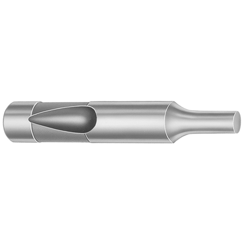
Ball Lock Regular Ejector Punches Heavy Duty, Inch, XNP Coating
Ball Lock Regular ejector punches Heavy Duty, Inch, with XNP coating are designed to deliver stable locking and consistent ejection performance in punch and die assemblies. The standardized Dayton LAMINA part format helps teams match components accurately during tool maintenance.
- Ball lock design supports secure retention and controlled ejection
- XNP coating enhances wear resistance for long production runs
- Tooling-ready punch tip options for different contact profiles
- Built for heavy-duty inch tooling applications in production dies
Specifications
1950 configurations available
| Tip Shape | Material | D (Shank dia.) (in) | Standard Point Length & L (Length) (coded inch) | [B] Point Length B & L (Length) (coded inch) | [C] Point Length B & L (Length) (coded inch) | [D] Point Length B & L (Length) (coded inch) | P Dimension (in) | W Dimension (in) | R Dimension (in) |
|---|---|---|---|---|---|---|---|---|---|
| H | M2 | 37 (0.3750") | 250 ~ 600 | - | - | - | 0.05 ~ 0.374 | 0.05 ~ 0.124 | - |
| H | M2 | 37 (0.3750") | 250 ~ 600 | - | - | - | 0.05 ~ 0.374 | 0.062 ~ 0.374 | - |
| H | PS4 | 37 (0.3750") | 250 ~ 600 | - | - | - | 0.05 ~ 0.374 | 0.05 ~ 0.124 | - |
| H | PS4 | 37 (0.3750") | 250 ~ 600 | - | - | - | 0.05 ~ 0.374 | 0.062 ~ 0.374 | - |
| H | M2 | 37 (0.3750") | - | 250 ~ 600 | - | - | 0.05 ~ 0.374 | 0.05 ~ 0.124 | - |
| H | M2 | 37 (0.3750") | - | 250 ~ 600 | - | - | 0.05 ~ 0.374 | 0.062 ~ 0.374 | - |
| H | PS4 | 37 (0.3750") | - | 250 ~ 600 | - | - | 0.05 ~ 0.374 | 0.05 ~ 0.124 | - |
| H | PS4 | 37 (0.3750") | - | 250 ~ 600 | - | - | 0.05 ~ 0.374 | 0.062 ~ 0.374 | - |
| H | M2 | 37 (0.3750") | - | - | 250 ~ 600 | - | 0.05 ~ 0.374 | 0.05 ~ 0.124 | - |
| H | M2 | 37 (0.3750") | - | - | 250 ~ 600 | - | 0.05 ~ 0.374 | 0.062 ~ 0.374 | - |
| H | PS4 | 37 (0.3750") | - | - | 250 ~ 600 | - | 0.05 ~ 0.374 | 0.05 ~ 0.124 | - |
| H | PS4 | 37 (0.3750") | - | - | 250 ~ 600 | - | 0.05 ~ 0.374 | 0.062 ~ 0.374 | - |
| H | M2 | 50 (0.5000") | 250 ~ 700 | - | - | - | 0.093 ~ 0.186 | 0.093 ~ 0.186 | - |
| H | M2 | 50 (0.5000") | 250 ~ 700 | - | - | - | 0.093 ~ 0.186 | 0.187 ~ 0.499 | - |
| H | M2 | 50 (0.5000") | 250 ~ 700 | - | - | - | 0.187 ~ 0.499 | 0.093 ~ 0.186 | - |
| H | M2 | 50 (0.5000") | 250 ~ 700 | - | - | - | 0.187 ~ 0.499 | 0.187 ~ 0.499 | - |
| H | PS4 | 50 (0.5000") | 250 ~ 700 | - | - | - | 0.093 ~ 0.186 | 0.093 ~ 0.186 | - |
| H | PS4 | 50 (0.5000") | 250 ~ 700 | - | - | - | 0.093 ~ 0.186 | 0.187 ~ 0.499 | - |
| H | PS4 | 50 (0.5000") | 250 ~ 700 | - | - | - | 0.187 ~ 0.499 | 0.093 ~ 0.186 | - |
| H | PS4 | 50 (0.5000") | 250 ~ 700 | - | - | - | 0.187 ~ 0.499 | 0.187 ~ 0.499 | - |
| H | M2 | 50 (0.5000") | - | 250 ~ 700 | - | - | 0.093 ~ 0.186 | 0.093 ~ 0.186 | - |
| H | M2 | 50 (0.5000") | - | 250 ~ 700 | - | - | 0.093 ~ 0.186 | 0.187 ~ 0.499 | - |
| H | M2 | 50 (0.5000") | - | 250 ~ 700 | - | - | 0.187 ~ 0.499 | 0.093 ~ 0.186 | - |
| H | M2 | 50 (0.5000") | - | 250 ~ 700 | - | - | 0.187 ~ 0.499 | 0.187 ~ 0.499 | - |
| H | PS4 | 50 (0.5000") | - | 250 ~ 700 | - | - | 0.093 ~ 0.186 | 0.093 ~ 0.186 | - |
| H | PS4 | 50 (0.5000") | - | 250 ~ 700 | - | - | 0.093 ~ 0.186 | 0.187 ~ 0.499 | - |
| H | PS4 | 50 (0.5000") | - | 250 ~ 700 | - | - | 0.187 ~ 0.499 | 0.093 ~ 0.186 | - |
| H | PS4 | 50 (0.5000") | - | 250 ~ 700 | - | - | 0.187 ~ 0.499 | 0.187 ~ 0.499 | - |
| H | M2 | 50 (0.5000") | - | - | 250 ~ 700 | - | 0.093 ~ 0.186 | 0.093 ~ 0.186 | - |
| H | M2 | 50 (0.5000") | - | - | 250 ~ 700 | - | 0.093 ~ 0.186 | 0.187 ~ 0.499 | - |
| H | M2 | 50 (0.5000") | - | - | 250 ~ 700 | - | 0.187 ~ 0.499 | 0.093 ~ 0.186 | - |
| H | M2 | 50 (0.5000") | - | - | 250 ~ 700 | - | 0.187 ~ 0.499 | 0.187 ~ 0.499 | - |
| H | PS4 | 50 (0.5000") | - | - | 250 ~ 700 | - | 0.093 ~ 0.186 | 0.093 ~ 0.186 | - |
| H | PS4 | 50 (0.5000") | - | - | 250 ~ 700 | - | 0.093 ~ 0.186 | 0.187 ~ 0.499 | - |
| H | PS4 | 50 (0.5000") | - | - | 250 ~ 700 | - | 0.187 ~ 0.499 | 0.093 ~ 0.186 | - |
| H | PS4 | 50 (0.5000") | - | - | 250 ~ 700 | - | 0.187 ~ 0.499 | 0.187 ~ 0.499 | - |
| H | M2 | 50 (0.5000") | - | - | - | 275 ~ 700 | 0.093 ~ 0.186 | 0.093 ~ 0.186 | - |
| H | M2 | 50 (0.5000") | - | - | - | 275 ~ 700 | 0.093 ~ 0.186 | 0.187 ~ 0.499 | - |
| H | M2 | 50 (0.5000") | - | - | - | 275 ~ 700 | 0.187 ~ 0.499 | 0.093 ~ 0.186 | - |
| H | M2 | 50 (0.5000") | - | - | - | 275 ~ 700 | 0.187 ~ 0.499 | 0.187 ~ 0.499 | - |
| H | PS4 | 50 (0.5000") | - | - | - | 275 ~ 700 | 0.093 ~ 0.186 | 0.093 ~ 0.186 | - |
| H | PS4 | 50 (0.5000") | - | - | - | 275 ~ 700 | 0.093 ~ 0.186 | 0.187 ~ 0.499 | - |
| H | PS4 | 50 (0.5000") | - | - | - | 275 ~ 700 | 0.187 ~ 0.499 | 0.093 ~ 0.186 | - |
| H | PS4 | 50 (0.5000") | - | - | - | 275 ~ 700 | 0.187 ~ 0.499 | 0.187 ~ 0.499 | - |
| H | M2 | 62 (0.6250") | 250 ~ 700 | - | - | - | 0.25 ~ 0.624 | 0.25 ~ 0.624 | - |
| H | M2 | 62 (0.6250") | 250 ~ 700 | - | - | - | 0.25 ~ 0.624 | 0.125 ~ 0.249 | - |
| H | M2 | 62 (0.6250") | 250 ~ 700 | - | - | - | 0.125 ~ 0.249 | 0.25 ~ 0.624 | - |
| H | M2 | 62 (0.6250") | 250 ~ 700 | - | - | - | 0.125 ~ 0.249 | 0.125 ~ 0.249 | - |
| H | PS4 | 62 (0.6250") | 250 ~ 700 | - | - | - | 0.25 ~ 0.624 | 0.25 ~ 0.624 | - |
| H | PS4 | 62 (0.6250") | 250 ~ 700 | - | - | - | 0.25 ~ 0.624 | 0.125 ~ 0.249 | - |
Product Guide
Application Scenarios+
Ball-lock ejector punches are used inside punch-and-die tooling to provide stable ejector action while maintaining secure retention under repeated cycling. This heavy-duty inch variant, supplied with an XNP coating, is especially suited for applications where long production runs demand consistent ejection without premature wear at the contact interface.
- Tool & die work for general forming and stamping: choose tip shapes (H, J, K, L, N, O, R, V, X, Y, Z) to match the required contact profile, helping keep ejection force transfer predictable.
- Automotive and industrial components molds: the ball-lock design supports controlled ejection and helps prevent punch shift during wear cycles.
- Maintenance-focused tooling assemblies: the standardized Dayton LAMINA part format simplifies component matching during service, reducing downtime during punch replacement.
Where wear is the limiting factor, the XNP coating improves wear resistance, supporting reliable locking and consistent ejector performance across cycles.
Material & Process Details+
This series is offered in M2 and PS4 material options, enabling selection based on wear resistance and toughness needs. M2 is a high-speed steel class commonly selected for tooling interfaces that see abrasive wear and frequent cycles. PS4 is a tool steel option intended for durable performance in die components, typically chosen when a balance of strength and wear resistance is required for production service.
- Hardness/heat treatment: the provided metadata does not specify the exact heat-treat condition (e.g., quenched & tempered or nitrided) or hardness in HRC for M2 or PS4, so the final hardness should be confirmed from the specific product lot/spec sheet.
- Wear vs. toughness trade-off: M2 generally supports higher wear resistance in cutting/tooling applications, while the alternative material may offer a different toughness/wear balance depending on its specified heat treatment.
The XNP coating complements the base steel by reducing surface wear at the ejector contact area during repetitive ejection.
Sizing & Selection Guide+
Select dimensions by matching the ejector punch shank diameter and coded point length to the mold’s guide/support geometry and the required ejection contact. This series provides D (shank dia.) from 37 ~ 125 in and Standard point length L coded inch ranges such as 250 ~ 600, 250 ~ 700, 275 ~ 700, and 300 ~ 700, depending on the selected variant. Additional coded lengths are also shown as B and C point length ranges with the same listed bracketed options.
- Match cavity/core clearance: use the specified L (and whether B/C/D point length options apply) to ensure the punch reaches the intended ejection travel without bottoming.
- Check fit and tolerances: the metadata lists P dimension from 0.05 ~ 1 in, W from 0.05 ~ 0.5 in, and R at 0.007; confirm these features against your guide/retainer interfaces.
- Configure tip shape: choose the tip shape (H, J, K, L, N, O, R, V, X, Y, Z) to match the required contact profile for controlled ejection.
Confirm whether your assembly expects fixed vs. variant-dependent coded lengths before finalizing the BOM.
Frequently Asked Questions
Which tip shapes (H, J, K, L, N, O, R, V, X, Y, Z) are available for this ball-lock ejector punch series, and how do they affect contact profile?+
This series supports multiple tip shapes: H, J, K, L, N, O, R, V, X, Y, Z. Each selection is intended to match a specific ejector contact profile in punch-and-die assemblies. When designing the cavity/core interface, select the tip shape that fits your contact geometry to help maintain controlled ejection.
What material options are offered (M2 vs PS4) for the heavy-duty inch ball-lock regular ejector punches?+
The series lists M2 and PS4 as available materials. The base material choice should be aligned with your wear and toughness requirements for the ejector contact zone. The provided metadata does not include exact HRC or heat-treatment state for either option, so verify the specified heat-treat condition from the item’s detailed spec/lot documentation.
How do I select the correct shank diameter D and coded point length L for the mold ejector travel?+
Use D (shank dia.) in the range 37 ~ 125 in and choose a standard point length L coded range that matches your clearance and required engagement. Available coded ranges include 250 ~ 600, 250 ~ 700, 275 ~ 700, and 300 ~ 700 (variant dependent). Confirm whether your assembly uses standard L only or also involves point lengths labeled B, C, and/or D features.
What are the P, W, and R dimensions, and are they critical for fit with ejector guides or retainers?+
The metadata specifies P = 0.05 ~ 1 in, W = 0.05 ~ 0.5 in, and R = 0.007. These dimensions are commonly associated with locating/geometry features that can affect fit and alignment within the mold’s guide/retainer interfaces. Validate these values against your drawing requirements to ensure proper retention and smooth ejector action.
Does the XNP coating change wear performance for high-cycle tool & die applications?+
This series includes an XNP coating and is intended to improve wear resistance for production tool & die usage. In high-cycle conditions, coating performance helps reduce surface wear at the ejector contact interface, supporting consistent ejection. For full wear expectations, confirm the coating system details and the underlying steel heat-treatment condition for your chosen M2 or PS4 material variant.
Related Products


Need Custom Specifications?
Our engineering team can help with custom configurations, material selection, and volume pricing.