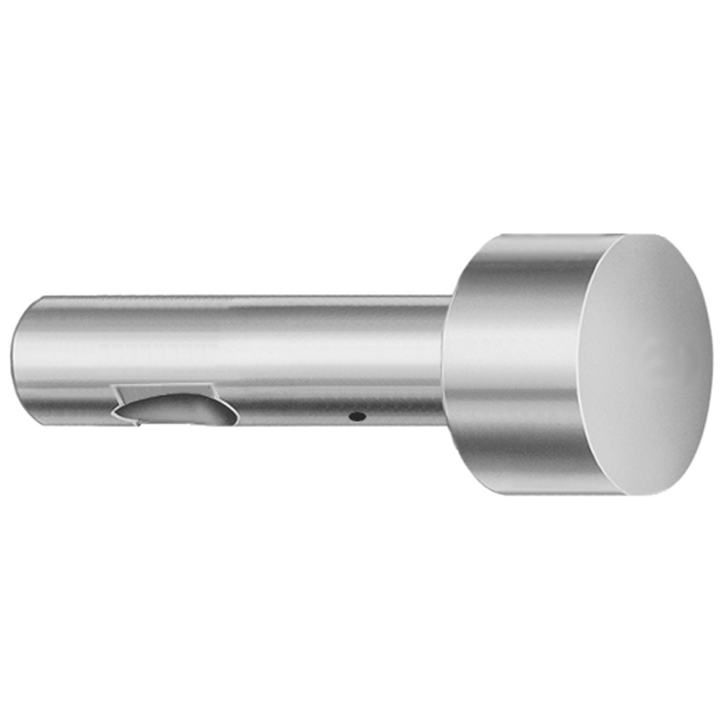
Ball Lock Regular Ejector Punch Blanks Light Duty, Inch
Ball lock regular ejector punch blanks (light duty, inch) are engineered for economical punch sets in die and mold shops, delivering reliable ball-lock retention for repeatable part ejection. DAYTON standardized part formats simplify procurement and assembly.
- Ball-lock design improves alignment and secure punch seating in the tooling system
- Available steel options with consistent hardening for dependable wear resistance
- Tip shapes (R, X, K, O, H, L, J, N, V, Y, Z) support different cavity geometries
- Common choice for light-duty production runs requiring stable ejector performance
Specifications
228 configurations available
| Tip Shape | Material | D (Shank dia.) (in) | L (Length) (coded inch) | P Dimension (in) | W Dimension (in) | R Dimension (in) |
|---|---|---|---|---|---|---|
| H | M2 | 37 (0.3750") | 250 ~ 450 | 0.376 ~ 0.875 | 0.062 ~ 0.124 | - |
| H | M2 | 37 (0.3750") | 250 ~ 450 | 0.376 ~ 0.875 | 0.125 ~ 0.875 | - |
| H | A2 | 37 (0.3750") | 250 ~ 450 | 0.376 ~ 0.875 | 0.062 ~ 0.124 | - |
| H | A2 | 37 (0.3750") | 250 ~ 450 | 0.376 ~ 0.875 | 0.125 ~ 0.875 | - |
| H | M2 | 50 (0.5000") | 250 ~ 450 | 0.501 ~ 1.25 | 0.158 ~ 0.187 | - |
| H | M2 | 50 (0.5000") | 250 ~ 450 | 0.501 ~ 1.25 | 0.188 ~ 1.25 | - |
| H | A2 | 50 (0.5000") | 250 ~ 450 | 0.501 ~ 1.25 | 0.158 ~ 0.187 | - |
| H | A2 | 50 (0.5000") | 250 ~ 450 | 0.501 ~ 1.25 | 0.188 ~ 1.25 | - |
| H | M2 | 62 (0.6250") | 250 ~ 450 | 0.626 ~ 1.5 | 0.25 ~ 1.5 | - |
| H | M2 | 62 (0.6250") | 250 ~ 450 | 0.626 ~ 1.5 | 0.158 ~ 0.249 | - |
| H | A2 | 62 (0.6250") | 250 ~ 450 | 0.626 ~ 1.5 | 0.25 ~ 1.5 | - |
| H | A2 | 62 (0.6250") | 250 ~ 450 | 0.626 ~ 1.5 | 0.158 ~ 0.249 | - |
| H | M2 | 75 (0.7500") | 250 ~ 450 | 0.751 ~ 1.5 | 0.235 ~ 0.311 | - |
| H | M2 | 75 (0.7500") | 250 ~ 450 | 0.751 ~ 1.5 | 0.312 ~ 1.5 | - |
| H | A2 | 75 (0.7500") | 250 ~ 450 | 0.751 ~ 1.5 | 0.235 ~ 0.311 | - |
| H | A2 | 75 (0.7500") | 250 ~ 450 | 0.751 ~ 1.5 | 0.312 ~ 1.5 | - |
| H | M2 | 87 (0.8750") | 250 ~ 450 | 0.876 ~ 1.75 | 0.235 ~ 0.374 | - |
| H | M2 | 87 (0.8750") | 250 ~ 450 | 0.876 ~ 1.75 | 0.375 ~ 1.75 | - |
| H | A2 | 87 (0.8750") | 250 ~ 450 | 0.876 ~ 1.75 | 0.235 ~ 0.374 | - |
| H | A2 | 87 (0.8750") | 250 ~ 450 | 0.876 ~ 1.75 | 0.375 ~ 1.75 | - |
| H | M2 | 100 (1.0000") | 250 ~ 450 | 1.001 ~ 1.75 | 0.235 ~ 0.436 | - |
| H | M2 | 100 (1.0000") | 250 ~ 450 | 1.001 ~ 1.75 | 0.437 ~ 1.75 | - |
| H | A2 | 100 (1.0000") | 250 ~ 450 | 1.001 ~ 1.75 | 0.235 ~ 0.436 | - |
| H | A2 | 100 (1.0000") | 250 ~ 450 | 1.001 ~ 1.75 | 0.437 ~ 1.75 | - |
| J | M2 | 37 (0.3750") | 250 ~ 450 | 0.376 ~ 0.875 | 0.062 ~ 0.124 | - |
| J | M2 | 37 (0.3750") | 250 ~ 450 | 0.376 ~ 0.875 | 0.125 ~ 0.875 | - |
| J | A2 | 37 (0.3750") | 250 ~ 450 | 0.376 ~ 0.875 | 0.062 ~ 0.124 | - |
| J | A2 | 37 (0.3750") | 250 ~ 450 | 0.376 ~ 0.875 | 0.125 ~ 0.875 | - |
| J | M2 | 50 (0.5000") | 250 ~ 450 | 0.501 ~ 1.25 | 0.158 ~ 0.187 | - |
| J | M2 | 50 (0.5000") | 250 ~ 450 | 0.501 ~ 1.25 | 0.188 ~ 1.25 | - |
| J | A2 | 50 (0.5000") | 250 ~ 450 | 0.501 ~ 1.25 | 0.158 ~ 0.187 | - |
| J | A2 | 50 (0.5000") | 250 ~ 450 | 0.501 ~ 1.25 | 0.188 ~ 1.25 | - |
| J | M2 | 62 (0.6250") | 250 ~ 450 | 0.626 ~ 1.5 | 0.25 ~ 1.5 | - |
| J | M2 | 62 (0.6250") | 250 ~ 450 | 0.626 ~ 1.5 | 0.158 ~ 0.249 | - |
| J | A2 | 62 (0.6250") | 250 ~ 450 | 0.626 ~ 1.5 | 0.25 ~ 1.5 | - |
| J | A2 | 62 (0.6250") | 250 ~ 450 | 0.626 ~ 1.5 | 0.158 ~ 0.249 | - |
| J | M2 | 75 (0.7500") | 250 ~ 450 | 0.751 ~ 1.5 | 0.235 ~ 0.311 | - |
| J | M2 | 75 (0.7500") | 250 ~ 450 | 0.751 ~ 1.5 | 0.312 ~ 1.5 | - |
| J | A2 | 75 (0.7500") | 250 ~ 450 | 0.751 ~ 1.5 | 0.235 ~ 0.311 | - |
| J | A2 | 75 (0.7500") | 250 ~ 450 | 0.751 ~ 1.5 | 0.312 ~ 1.5 | - |
| J | M2 | 87 (0.8750") | 250 ~ 450 | 0.876 ~ 1.75 | 0.235 ~ 0.374 | - |
| J | M2 | 87 (0.8750") | 250 ~ 450 | 0.876 ~ 1.75 | 0.375 ~ 1.75 | - |
| J | A2 | 87 (0.8750") | 250 ~ 450 | 0.876 ~ 1.75 | 0.235 ~ 0.374 | - |
| J | A2 | 87 (0.8750") | 250 ~ 450 | 0.876 ~ 1.75 | 0.375 ~ 1.75 | - |
| J | M2 | 100 (1.0000") | 250 ~ 450 | 1.001 ~ 1.75 | 0.235 ~ 0.436 | - |
| J | M2 | 100 (1.0000") | 250 ~ 450 | 1.001 ~ 1.75 | 0.437 ~ 1.75 | - |
| J | A2 | 100 (1.0000") | 250 ~ 450 | 1.001 ~ 1.75 | 0.235 ~ 0.436 | - |
| J | A2 | 100 (1.0000") | 250 ~ 450 | 1.001 ~ 1.75 | 0.437 ~ 1.75 | - |
| K | M2 | 37 (0.3750") | 250 ~ 450 | 0.376 ~ 0.875 | 0.062 ~ 0.124 | 0.007 ~ 0.4375 |
| K | M2 | 37 (0.3750") | 250 ~ 450 | 0.376 ~ 0.875 | 0.125 ~ 0.875 | 0.007 ~ 0.4375 |
Product Guide
Application Scenarios+
Ball-lock regular ejector punch blanks (light duty, inch) are used to build economical ejector systems for production molds where stable, repeatable part release is required.
- Automotive and appliance connector molds: Ball-lock retention helps keep the punch seated during cycling, reducing movement that can lead to uneven ejection marks. Select the appropriate tip shape (R, X, K, O, H, L, J, N, V, Y, Z) to match the gate/cavity geometry and eject where contact pressure must be consistent.
- Consumer plastic housing and snap-fit parts: The light-duty configuration suits moderate loads and helps maintain ejector alignment for predictable release. Standardized inch shanks and lengths simplify punch set assembly and maintenance.
- General die and mold press tooling: Using this variant with known hardenable steel options supports dependable wear performance over repeated cycles, making it suitable for light-to-moderate production runs.
Material & Process Details+
These ejector punch blanks are offered in M2 and A2 tool steels. M2 is an AISI M2 equivalent high-speed steel grade selected for strong wear resistance; it typically provides a good balance of hardness and life under repeated sliding/contact. A2 is an AISI A2 equivalent work/hot-work tool steel that is often chosen where toughness and wear performance must be balanced for press tooling.
- Wear vs. toughness: M2 generally favors higher abrasion resistance, while A2 can offer improved toughness characteristics for lighter-duty ejection scenarios.
- Heat treatment: Both grades are supplied for hardened service and are commonly quenched and tempered to reach the functional hardness required for ejector wear. Exact hardness targets and temper conditions depend on the supplier’s processing recipe and your toolmaker’s specification.
- Manufacturing: Precision grinding of the shank and tip helps ensure stable seating within the ball-lock system and consistent tip-to-cavity contact.
Sizing & Selection Guide+
Select dimensions by matching the punch shank diameter, working length, and tip profile to your cavity/core ejection needs.
- Shank diameter (D): Choose from 0.3750" (37), 0.5000" (50), 0.6250" (62), 0.7500" (75), 0.8750" (87), or 1.0000" (100). D must correspond to the punch retention/guide requirements of your ball-lock ejector system.
- Length (L): Available lengths are 250 to 450 (coded inch range). Confirm the required stick-out to achieve correct ejector travel without bottoming.
- Tip geometry: Pick the specified Tip Shape (H, J, K, L, N, O, R, V, X, Y, Z) and verify that your cavity contact envelope can accept the P and R ranges. P spans 0.376–0.875, 0.501–1.25, 0.626–1.5, 0.751–1.5, 0.876–1.75, and 1.001–1.75 depending on configuration; R spans 0.007–0.4375 up to 0.007–0.875.
Tolerance & fit: Because ball-lock seating is sensitive to alignment, maintain the intended clearance between punch and its housing/retainer. If your cavity design is tight, validate tip contact location using CAD before final cut of the ejector plate and retention bores.
Frequently Asked Questions
Which tip shapes are compatible with regular ejector punch ball-lock assemblies in this light-duty inch series?+
This series supports multiple Tip Shape options: H, J, K, L, N, O, R, V, X, Y, Z. Select the profile that matches your cavity/core contact geometry so the ejector applies consistent pushing area and minimizes point loading. Pair the tip selection with the correct shank diameter (D) and length (L) to maintain proper seating and travel.
How do I choose between M2 and A2 for an ejector punch blank when wear life versus toughness matters?+
This product is available in M2 (AISI M2 equivalent) and A2 (AISI A2 equivalent). If your application has higher abrasion/contact wear, M2 is typically favored for stronger wear resistance. If the toolmaker prioritizes a more balanced performance for press tooling and ejection loads, A2 can be a suitable alternative.
What shank diameter (D) options are available, and how do they affect fit in the ball-lock punch retention system?+
The available D (shank diameter) values are 37 (0.3750"), 50 (0.5000"), 62 (0.6250"), 75 (0.7500"), 87 (0.8750"), and 100 (1.0000"). Your retention/guide bores must be sized to accept the selected diameter so the ball-lock can seat securely without misalignment. Confirm clearance and alignment before final machining of the ejector plate.
How should I match punch length (L) to required ejector travel without risking bottoming?+
For this series, L is specified in the coded inch range of 250 to 450. Choose the length so the punch has enough stick-out to achieve full part separation at peak cavity pressure, while still leaving margin to prevent bottoming in the closed condition. Validate the required travel path in your ejector stroke simulation or CAD assembly.
What do P and R dimension ranges mean for tip contact and cavity compatibility?+
P and R define the tip’s dimensional envelope and curvature/contact characteristics. P ranges from 0.376–0.875 up to 1.001–1.75 depending on the configuration, and R ranges from 0.007–0.4375 up to 0.007–0.875. Ensure your cavity/core contact area can accommodate these ranges and that the tip shape you select (H/J/K/L/N/O/R/V/X/Y/Z) aligns with the ejector contact point.
Related Products


Need Custom Specifications?
Our engineering team can help with custom configurations, material selection, and volume pricing.