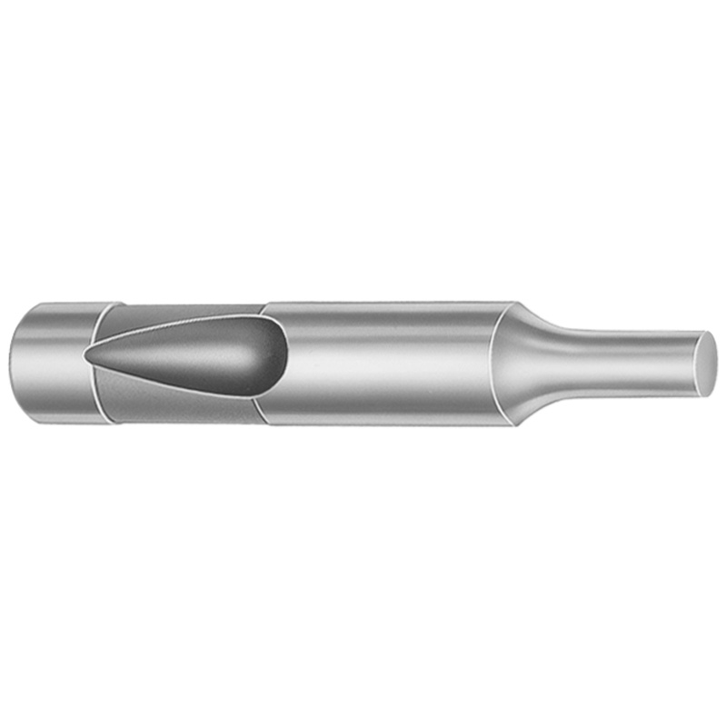
DAYTON Ball Lock Regular Ejector Punches - Heavy Duty, Inch
Ball Lock Regular Ejector Punches - Heavy Duty, Inch from DAYTON are designed for dependable part ejection in production dies. The XNAD coating supports longer service life under demanding stamping and forming cycles.
- Ball lock regular design improves retention and stable punch guidance in dies.
- XNAD coated punch surface helps resist wear during repeated ejection events.
- Matched point and coded inch lengths support consistent assembly fit in tooling.
- Use in heavy duty progressive, blanking, and forming operations where dimensional stability matters.
Specifications
1950 configurations available
| Tip Shape | Material | D (Shank dia.) (in) | Standard Point Length & L (Length) (coded inch) | [B] Point Length B & L (Length) (coded inch) | [C] Point Length B & L (Length) (coded inch) | [D] Point Length B & L (Length) (coded inch) | P Dimension (in) | W Dimension (in) | R Dimension (in) |
|---|---|---|---|---|---|---|---|---|---|
| H | M2 | 37 (0.3750") | 250 ~ 600 | - | - | - | 0.05 ~ 0.374 | 0.05 ~ 0.124 | - |
| H | M2 | 37 (0.3750") | 250 ~ 600 | - | - | - | 0.05 ~ 0.374 | 0.062 ~ 0.374 | - |
| H | PS4 | 37 (0.3750") | 250 ~ 600 | - | - | - | 0.05 ~ 0.374 | 0.05 ~ 0.124 | - |
| H | PS4 | 37 (0.3750") | 250 ~ 600 | - | - | - | 0.05 ~ 0.374 | 0.062 ~ 0.374 | - |
| H | M2 | 37 (0.3750") | - | 250 ~ 600 | - | - | 0.05 ~ 0.374 | 0.05 ~ 0.124 | - |
| H | M2 | 37 (0.3750") | - | 250 ~ 600 | - | - | 0.05 ~ 0.374 | 0.062 ~ 0.374 | - |
| H | PS4 | 37 (0.3750") | - | 250 ~ 600 | - | - | 0.05 ~ 0.374 | 0.05 ~ 0.124 | - |
| H | PS4 | 37 (0.3750") | - | 250 ~ 600 | - | - | 0.05 ~ 0.374 | 0.062 ~ 0.374 | - |
| H | M2 | 37 (0.3750") | - | - | 250 ~ 600 | - | 0.05 ~ 0.374 | 0.05 ~ 0.124 | - |
| H | M2 | 37 (0.3750") | - | - | 250 ~ 600 | - | 0.05 ~ 0.374 | 0.062 ~ 0.374 | - |
| H | PS4 | 37 (0.3750") | - | - | 250 ~ 600 | - | 0.05 ~ 0.374 | 0.05 ~ 0.124 | - |
| H | PS4 | 37 (0.3750") | - | - | 250 ~ 600 | - | 0.05 ~ 0.374 | 0.062 ~ 0.374 | - |
| H | M2 | 50 (0.5000") | 250 ~ 700 | - | - | - | 0.093 ~ 0.186 | 0.093 ~ 0.186 | - |
| H | M2 | 50 (0.5000") | 250 ~ 700 | - | - | - | 0.093 ~ 0.186 | 0.187 ~ 0.499 | - |
| H | M2 | 50 (0.5000") | 250 ~ 700 | - | - | - | 0.187 ~ 0.499 | 0.093 ~ 0.186 | - |
| H | M2 | 50 (0.5000") | 250 ~ 700 | - | - | - | 0.187 ~ 0.499 | 0.187 ~ 0.499 | - |
| H | PS4 | 50 (0.5000") | 250 ~ 700 | - | - | - | 0.093 ~ 0.186 | 0.093 ~ 0.186 | - |
| H | PS4 | 50 (0.5000") | 250 ~ 700 | - | - | - | 0.093 ~ 0.186 | 0.187 ~ 0.499 | - |
| H | PS4 | 50 (0.5000") | 250 ~ 700 | - | - | - | 0.187 ~ 0.499 | 0.093 ~ 0.186 | - |
| H | PS4 | 50 (0.5000") | 250 ~ 700 | - | - | - | 0.187 ~ 0.499 | 0.187 ~ 0.499 | - |
| H | M2 | 50 (0.5000") | - | 250 ~ 700 | - | - | 0.093 ~ 0.186 | 0.093 ~ 0.186 | - |
| H | M2 | 50 (0.5000") | - | 250 ~ 700 | - | - | 0.093 ~ 0.186 | 0.187 ~ 0.499 | - |
| H | M2 | 50 (0.5000") | - | 250 ~ 700 | - | - | 0.187 ~ 0.499 | 0.093 ~ 0.186 | - |
| H | M2 | 50 (0.5000") | - | 250 ~ 700 | - | - | 0.187 ~ 0.499 | 0.187 ~ 0.499 | - |
| H | PS4 | 50 (0.5000") | - | 250 ~ 700 | - | - | 0.093 ~ 0.186 | 0.093 ~ 0.186 | - |
| H | PS4 | 50 (0.5000") | - | 250 ~ 700 | - | - | 0.093 ~ 0.186 | 0.187 ~ 0.499 | - |
| H | PS4 | 50 (0.5000") | - | 250 ~ 700 | - | - | 0.187 ~ 0.499 | 0.093 ~ 0.186 | - |
| H | PS4 | 50 (0.5000") | - | 250 ~ 700 | - | - | 0.187 ~ 0.499 | 0.187 ~ 0.499 | - |
| H | M2 | 50 (0.5000") | - | - | 250 ~ 700 | - | 0.093 ~ 0.186 | 0.093 ~ 0.186 | - |
| H | M2 | 50 (0.5000") | - | - | 250 ~ 700 | - | 0.093 ~ 0.186 | 0.187 ~ 0.499 | - |
| H | M2 | 50 (0.5000") | - | - | 250 ~ 700 | - | 0.187 ~ 0.499 | 0.093 ~ 0.186 | - |
| H | M2 | 50 (0.5000") | - | - | 250 ~ 700 | - | 0.187 ~ 0.499 | 0.187 ~ 0.499 | - |
| H | PS4 | 50 (0.5000") | - | - | 250 ~ 700 | - | 0.093 ~ 0.186 | 0.093 ~ 0.186 | - |
| H | PS4 | 50 (0.5000") | - | - | 250 ~ 700 | - | 0.093 ~ 0.186 | 0.187 ~ 0.499 | - |
| H | PS4 | 50 (0.5000") | - | - | 250 ~ 700 | - | 0.187 ~ 0.499 | 0.093 ~ 0.186 | - |
| H | PS4 | 50 (0.5000") | - | - | 250 ~ 700 | - | 0.187 ~ 0.499 | 0.187 ~ 0.499 | - |
| H | M2 | 50 (0.5000") | - | - | - | 275 ~ 700 | 0.093 ~ 0.186 | 0.093 ~ 0.186 | - |
| H | M2 | 50 (0.5000") | - | - | - | 275 ~ 700 | 0.093 ~ 0.186 | 0.187 ~ 0.499 | - |
| H | M2 | 50 (0.5000") | - | - | - | 275 ~ 700 | 0.187 ~ 0.499 | 0.093 ~ 0.186 | - |
| H | M2 | 50 (0.5000") | - | - | - | 275 ~ 700 | 0.187 ~ 0.499 | 0.187 ~ 0.499 | - |
| H | PS4 | 50 (0.5000") | - | - | - | 275 ~ 700 | 0.093 ~ 0.186 | 0.093 ~ 0.186 | - |
| H | PS4 | 50 (0.5000") | - | - | - | 275 ~ 700 | 0.093 ~ 0.186 | 0.187 ~ 0.499 | - |
| H | PS4 | 50 (0.5000") | - | - | - | 275 ~ 700 | 0.187 ~ 0.499 | 0.093 ~ 0.186 | - |
| H | PS4 | 50 (0.5000") | - | - | - | 275 ~ 700 | 0.187 ~ 0.499 | 0.187 ~ 0.499 | - |
| H | M2 | 62 (0.6250") | 250 ~ 700 | - | - | - | 0.25 ~ 0.624 | 0.25 ~ 0.624 | - |
| H | M2 | 62 (0.6250") | 250 ~ 700 | - | - | - | 0.25 ~ 0.624 | 0.125 ~ 0.249 | - |
| H | M2 | 62 (0.6250") | 250 ~ 700 | - | - | - | 0.125 ~ 0.249 | 0.25 ~ 0.624 | - |
| H | M2 | 62 (0.6250") | 250 ~ 700 | - | - | - | 0.125 ~ 0.249 | 0.125 ~ 0.249 | - |
| H | PS4 | 62 (0.6250") | 250 ~ 700 | - | - | - | 0.25 ~ 0.624 | 0.25 ~ 0.624 | - |
| H | PS4 | 62 (0.6250") | 250 ~ 700 | - | - | - | 0.25 ~ 0.624 | 0.125 ~ 0.249 | - |
Product Guide
Application Scenarios+
This heavy-duty ball-lock regular ejector punch is used in inch-series injection stamping and forming die sets where consistent part release is required during high cycle production. The ball-lock retention style provides stable punch guidance and helps maintain correct positioning through repeated ejector strokes.
- Automotive and industrial connector housings: suited for progressive blanking/forming operations that demand reliable return-to-position, using the punch’s heavy-duty retention to reduce misalignment under load.
- Appliance and metal enclosure stampings: the XNAD-coated working surface improves wear resistance against frequent ejection events, supporting longer service life in abrasive, high-contact cycles.
- General purpose forming dies: matched point and coded inch lengths support repeatable assembly fit in tooling, helping engineers maintain dimensional stability across core/cavity-related components.
Choose among the available tip shapes (H, J, K, L, N, O, R, V, X, Y, Z) to align punch geometry with part ejection features.
Material & Process Details+
These ejector punches are offered in M2 or PS4 steel. M2 is a high-speed steel commonly selected for excellent wear resistance and good performance where repeated metal-to-metal contact occurs during ejection. PS4 is typically selected when a balance of machinability and durability is needed for tooling environments with demanding cycle counts.
- Wear resistance: M2 generally supports longer punch life under abrasive and repetitive ejection loading, which complements the XNAD coating referenced for improved wear behavior.
- Toughness trade-offs: higher wear grades can be less tolerant of severe edge shock if misaligned, so correct die alignment and proper return are important.
- Heat treatment state: the specific hardness (HRC) and heat-treatment recipe are not provided in the available specifications, so hardness should be confirmed via the manufacturer’s material/heat-treatment data for the selected grade.
Compare grades in the context of your ejection force, contact wear, and shock risk, then validate hardness and coating adhesion for your production cycle.
Sizing & Selection Guide+
Selection starts with matching the shank diameter (D) and the coded inch point length (L) to your die cavity/core layout. The provided D range is 37 ~ 125 in, and available L ranges include 250 ~ 600, 250 ~ 700, 275 ~ 700, and 300 ~ 700 (coded inch).
- Match shank diameter: ensure the ejector guide bore and retention features are sized to accept the selected D while preventing lateral play that can accelerate wear or cause return issues.
- Match point length: choose the L variant that provides the required protrusion for part release without over-travel into the die structure.
- Verify related length dimensions: point length can be specified as B & L (multiple ranges listed) or as C & L / D & L (e.g., D point length B & L: 275 ~ 700 or 300 ~ 700), so confirm which length system your tooling drawings reference.
- Geometry tuning: tip shape (H, J, K, L, N, O, R, V, X, Y, Z) can affect required contact area; use P (0.05 ~ 1) and W (0.05 ~ 0.5) dimensions as engineering references when matching pocketing or contact profiles.
Tolerance/fit values are not included in the provided data, so apply your die-standard clearance/fit and confirm fit by measuring the purchased shank and length.
Frequently Asked Questions
Which tip shapes (H/J/K/L/N/O/R/V/X/Y/Z) should be selected for reliable ball-lock ejector performance?+
How do I choose the correct shank diameter D for inch tooling?+
What coded inch length (L) options are available for this regular heavy-duty ejector punch?+
Is XNAD coating compatible with both M2 and PS4 materials for wear resistance?+
How should I use the P, W, and R dimensions when fitting ejectors into the die?+
Related Products


Need Custom Specifications?
Our engineering team can help with custom configurations, material selection, and volume pricing.