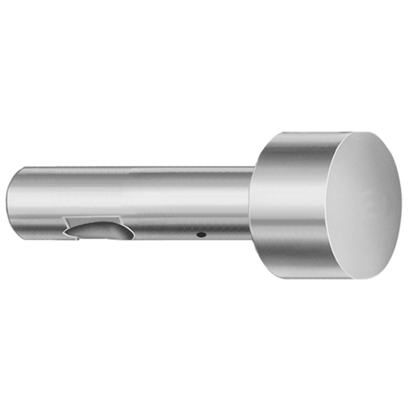
Inch Dayton XNAD Coated Ball Lock Ejector Punches - Light Duty
Ball lock ejector punches (XNAD coating) are designed for light-duty inch tooling, delivering consistent locking performance and stable ejection behavior in die and mold assemblies.
- Point larger than shank geometry supports efficient, controlled material ejection
- XNAD coated surface helps reduce wear and improves long-term durability
- Ball lock design enhances positional stability during repeated press cycles
- Compatible with standard mold systems for economical maintenance and fast replacement
Specifications
114 configurations available
| Tip Shape | D (Shank dia.) (in) | L (Length) (coded inch) | P Dimension (in) | W Dimension (in) | R Dimension (in) |
|---|---|---|---|---|---|
| H | 37 (0.3750") | 250 ~ 450 | 0.376 ~ 0.875 | 0.062 ~ 0.124 | - |
| H | 37 (0.3750") | 250 ~ 450 | 0.376 ~ 0.875 | 0.125 ~ 0.875 | - |
| H | 50 (0.5000") | 250 ~ 450 | 0.501 ~ 1.25 | 0.158 ~ 0.187 | - |
| H | 50 (0.5000") | 250 ~ 450 | 0.501 ~ 1.25 | 0.188 ~ 1.25 | - |
| H | 62 (0.6250") | 250 ~ 450 | 0.626 ~ 1.5 | 0.25 ~ 1.5 | - |
| H | 62 (0.6250") | 250 ~ 450 | 0.626 ~ 1.5 | 0.158 ~ 0.249 | - |
| H | 75 (0.7500") | 250 ~ 450 | 0.751 ~ 1.5 | 0.235 ~ 0.311 | - |
| H | 75 (0.7500") | 250 ~ 450 | 0.751 ~ 1.5 | 0.312 ~ 1.5 | - |
| H | 87 (0.8750") | 250 ~ 450 | 0.876 ~ 1.75 | 0.235 ~ 0.374 | - |
| H | 87 (0.8750") | 250 ~ 450 | 0.876 ~ 1.75 | 0.375 ~ 1.75 | - |
| H | 100 (1.0000") | 250 ~ 450 | 1.001 ~ 1.75 | 0.235 ~ 0.436 | - |
| H | 100 (1.0000") | 250 ~ 450 | 1.001 ~ 1.75 | 0.437 ~ 1.75 | - |
| J | 37 (0.3750") | 250 ~ 450 | 0.376 ~ 0.875 | 0.062 ~ 0.124 | - |
| J | 37 (0.3750") | 250 ~ 450 | 0.376 ~ 0.875 | 0.125 ~ 0.875 | - |
| J | 50 (0.5000") | 250 ~ 450 | 0.501 ~ 1.25 | 0.158 ~ 0.187 | - |
| J | 50 (0.5000") | 250 ~ 450 | 0.501 ~ 1.25 | 0.188 ~ 1.25 | - |
| J | 62 (0.6250") | 250 ~ 450 | 0.626 ~ 1.5 | 0.25 ~ 1.5 | - |
| J | 62 (0.6250") | 250 ~ 450 | 0.626 ~ 1.5 | 0.158 ~ 0.249 | - |
| J | 75 (0.7500") | 250 ~ 450 | 0.751 ~ 1.5 | 0.235 ~ 0.311 | - |
| J | 75 (0.7500") | 250 ~ 450 | 0.751 ~ 1.5 | 0.312 ~ 1.5 | - |
| J | 87 (0.8750") | 250 ~ 450 | 0.876 ~ 1.75 | 0.235 ~ 0.374 | - |
| J | 87 (0.8750") | 250 ~ 450 | 0.876 ~ 1.75 | 0.375 ~ 1.75 | - |
| J | 100 (1.0000") | 250 ~ 450 | 1.001 ~ 1.75 | 0.235 ~ 0.436 | - |
| J | 100 (1.0000") | 250 ~ 450 | 1.001 ~ 1.75 | 0.437 ~ 1.75 | - |
| K | 37 (0.3750") | 250 ~ 450 | 0.376 ~ 0.875 | 0.062 ~ 0.124 | 0.007 ~ 0.4375 |
| K | 37 (0.3750") | 250 ~ 450 | 0.376 ~ 0.875 | 0.125 ~ 0.875 | 0.007 ~ 0.4375 |
| K | 50 (0.5000") | 250 ~ 450 | 0.501 ~ 1.25 | 0.158 ~ 0.187 | 0.007 ~ 0.625 |
| K | 50 (0.5000") | 250 ~ 450 | 0.501 ~ 1.25 | 0.188 ~ 1.25 | 0.007 ~ 0.625 |
| K | 62 (0.6250") | 250 ~ 450 | 0.626 ~ 1.5 | 0.25 ~ 1.5 | 0.007 ~ 0.75 |
| K | 62 (0.6250") | 250 ~ 450 | 0.626 ~ 1.5 | 0.158 ~ 0.249 | 0.007 ~ 0.75 |
| K | 75 (0.7500") | 250 ~ 450 | 0.751 ~ 1.5 | 0.235 ~ 0.311 | 0.007 ~ 0.75 |
| K | 75 (0.7500") | 250 ~ 450 | 0.751 ~ 1.5 | 0.312 ~ 1.5 | 0.007 ~ 0.75 |
| K | 87 (0.8750") | 250 ~ 450 | 0.876 ~ 1.75 | 0.235 ~ 0.374 | 0.007 ~ 0.875 |
| K | 87 (0.8750") | 250 ~ 450 | 0.876 ~ 1.75 | 0.375 ~ 1.75 | 0.007 ~ 0.875 |
| K | 100 (1.0000") | 250 ~ 450 | 1.001 ~ 1.75 | 0.235 ~ 0.436 | 0.007 ~ 0.875 |
| K | 100 (1.0000") | 250 ~ 450 | 1.001 ~ 1.75 | 0.437 ~ 1.75 | 0.007 ~ 0.875 |
| L | 37 (0.3750") | 250 ~ 450 | 0.376 ~ 0.875 | 0.062 ~ 0.124 | - |
| L | 37 (0.3750") | 250 ~ 450 | 0.376 ~ 0.875 | 0.125 ~ 0.875 | - |
| L | 50 (0.5000") | 250 ~ 450 | 0.501 ~ 1.25 | 0.158 ~ 0.187 | - |
| L | 50 (0.5000") | 250 ~ 450 | 0.501 ~ 1.25 | 0.188 ~ 1.25 | - |
| L | 62 (0.6250") | 250 ~ 450 | 0.626 ~ 1.5 | 0.25 ~ 1.5 | - |
| L | 62 (0.6250") | 250 ~ 450 | 0.626 ~ 1.5 | 0.158 ~ 0.249 | - |
| L | 75 (0.7500") | 250 ~ 450 | 0.751 ~ 1.5 | 0.235 ~ 0.311 | - |
| L | 75 (0.7500") | 250 ~ 450 | 0.751 ~ 1.5 | 0.312 ~ 1.5 | - |
| L | 87 (0.8750") | 250 ~ 450 | 0.876 ~ 1.75 | 0.235 ~ 0.374 | - |
| L | 87 (0.8750") | 250 ~ 450 | 0.876 ~ 1.75 | 0.375 ~ 1.75 | - |
| L | 100 (1.0000") | 250 ~ 450 | 1.001 ~ 1.75 | 0.235 ~ 0.436 | - |
| L | 100 (1.0000") | 250 ~ 450 | 1.001 ~ 1.75 | 0.437 ~ 1.75 | - |
| N | 37 (0.3750") | 250 ~ 450 | - | 0.326 ~ 0.758 | - |
| N | 50 (0.5000") | 250 ~ 450 | - | 0.434 ~ 1.083 | - |
Product Guide
Application Scenarios+
This light-duty ball lock ejector punch family is used in inch injection mold tooling where reliable, repeatable ejector actuation is required without heavy wear loads. The XNAD coated surface supports stable punch travel and locking engagement, making it well suited for compact die sets and cost-sensitive maintenance programs.
- Automotive connector and small housing molds: Use when frequent press cycles demand positional stability from the ball-lock mechanism while keeping parting lines clean and ejection consistent.
- Consumer product housings and brackets: Ideal for molds that prioritize economical replacement and predictable ejection behavior, especially where shank guidance prevents deflection.
- Light-duty transfer or insert molding tooling: Beneficial when controlled material ejection is needed; the point larger than shank geometry helps manage material flow at the ejector interface.
Choose the appropriate tip shape (H, J, K, L, N, O, R, V, X, Y, Z) to match die/core undercuts and ejection clearance, leveraging the coated wear surface to extend service life.
Material & Process Details+
The provided variant specifies an XNAD coating to enhance surface wear resistance for light-duty ejector operation. While the exact steel grade, base hardness (HRC), and heat treatment state are not included in the supplied specifications, the coating is intended to reduce abrasive wear at the locking and sliding interfaces and to maintain stable fit over repeated cycles.
- Wear resistance vs. toughness: Coated surfaces typically improve sliding life; ensure ejector dimensions and guidance support alignment to avoid edge loading that can stress the underlying steel.
- Manufacturing process relevance: Coated ejector punches are typically ground and finished to maintain consistent ball-lock engagement; the coating then forms the final wear surface.
- Heat treatment: No specific quench & temper, nitriding, or pre-hardened state is listed in the provided data—confirm base steel and heat treatment during engineering review.
If you need a specific hardened base (e.g., for higher impact loading), request the steel grade and hardness profile for the exact series code.
Sizing & Selection Guide+
Select dimensions by matching the ejector punch to the mold cavity/core hole geometry and the required ejection clearance. This series provides fixed and variable sizes, so begin with the shank diameter and length, then verify the point and engagement geometry.
- Shank diameter D (in): Choose from 0.3750, 0.5000, 0.6250, 0.7500, 0.8750, 1.0000.
- Ejector length L (coded inch): Select within 250 ~ 450 (coded length). Match to your ejector stroke and stack-up to ensure full actuation without bottoming.
- Point/engagement geometry (P, W, R): Use the available ranges to set clearance and ball-lock interface fit. P varies in blocks (e.g., 0.376~0.875, 0.501~1.25, 0.626~1.5, up to 1.001~1.75). W ranges 0.062~0.867, and R ranges from 0.007~0.4375 up to 0.007~0.875 depending on configuration.
Because tolerances and fit classes are not specified in the input data, maintain proper guide and locking clearance per your mold design standards, and verify that chosen D and tip shape (H–Z) won’t interfere with cavity/core surfaces.
Frequently Asked Questions
Which shank diameter (D) choices are available for these inch ball-lock ejector punches, and how do I match them to mold guide holes?+
Available shank diameters are 0.3750, 0.5000, 0.6250, 0.7500, 0.8750, and 1.0000 in. Match D to the mold’s ejector guide and receiving hole diameter while maintaining your required clearance for smooth travel. Since tolerance/fit class is not provided in the spec sheet here, verify your internal hole/guide tolerance standard against the selected D.
How do I select the coded length L (250–450) to avoid bottoming during ejection?+
This series uses a coded inch length with a fixed range of L = 250 ~ 450. Size L to your ejector stack-up and required stroke so the punch fully actuates without contacting the bottom of the cavity/core support. Recheck mold open/close position and any spacer/plate thickness changes because the correct L depends on the complete tool build.
What do the variable P, W, and R ranges control in the ball-lock ejector geometry?+
The spec lists variable geometry parameters: P (in blocks), W from 0.062~0.867, and R from 0.007~0.4375 up to 0.007~0.875 depending on configuration. These dimensions influence the point/transition geometry that affects controlled material ejection and interface clearance. Select values that prevent interference with cavity/core surfaces while supporting stable ball-lock engagement.
How does the XNAD coating help in light-duty ejector applications, and what should I validate for fit stability?+
The XNAD coating is intended to improve wear resistance at the ejector’s working surface, helping maintain stable performance over repeated cycles. For fit stability, confirm that the selected D and tip shape (H/J/K/L/N/O/R/V/X/Y/Z) align with your locking and guidance features. Because the underlying steel grade and hardness (HRC) are not specified here, request the material and heat-treatment details if you expect higher abrasive loading.
Which tip shapes (H–Z) should be considered when designing for different ejection clearances?+
This series supports multiple tip shapes: H, J, K, L, N, O, R, V, X, Y, Z. Choose the tip shape based on the cavity/core geometry and the required clearance at the ejector point to avoid scraping or premature wear. Validate the combination of tip shape with the chosen P/W/R geometry to ensure smooth ejection without interference.
Related Products


Need Custom Specifications?
Our engineering team can help with custom configurations, material selection, and volume pricing.