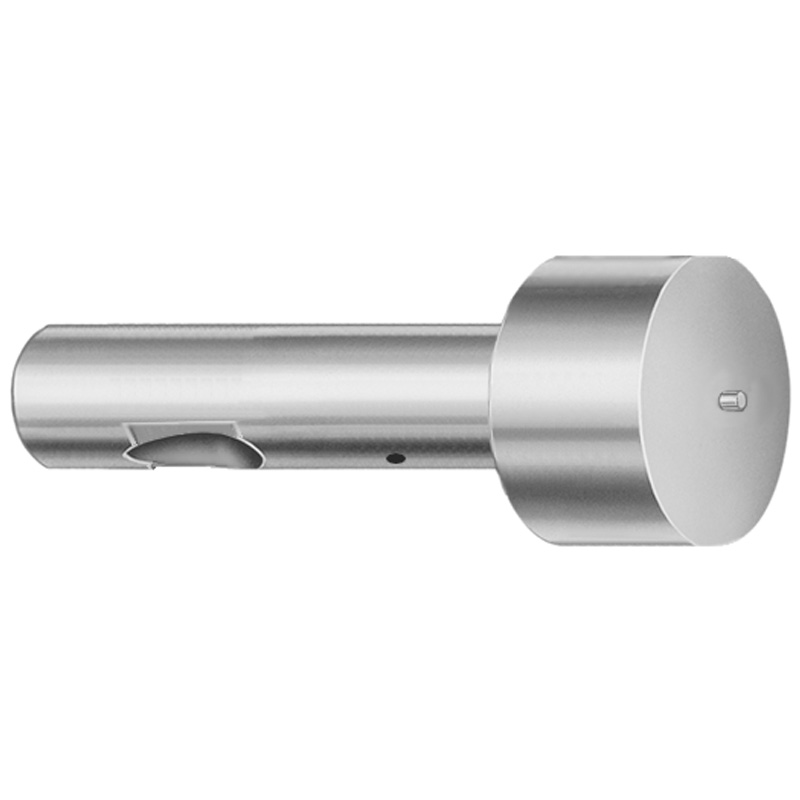
Ball Lock Ejector Punches - Light Duty, Inch, XAN DayTAN™ Coating
Ball Lock Ejector Punches for light-duty inch applications, built with an XAN DayTAN™ coating to help improve ejection smoothness and wear/corrosion performance in production tooling. The point is larger than the shank to support reliable locking action during operation.
- Point larger than shank geometry supports stable ball-lock retention
- XAN DayTAN™ coating designed for enhanced surface protection
- Precision-manufactured punch form for consistent fit in die assemblies
- Suitable for light-duty progressive and transfer die ejection systems
Specifications
114 configurations available
| Tip Shape | D (Shank dia.) (in) | Jektole group | L (Length) (coded inch) | P Dimension (in) | W Dimension (in) | R Dimension (in) |
|---|---|---|---|---|---|---|
| H | 37 (0.3750") | J4 | 250 ~ 450 | 0.376 ~ 0.875 | 0.062 ~ 0.124 | - |
| H | 37 (0.3750") | J4 | 250 ~ 450 | 0.376 ~ 0.875 | 0.125 ~ 0.875 | - |
| H | 50 (0.5000") | J6 | 250 ~ 450 | 0.501 ~ 1.25 | 0.158 ~ 0.187 | - |
| H | 50 (0.5000") | J6 | 250 ~ 450 | 0.501 ~ 1.25 | 0.188 ~ 1.25 | - |
| H | 62 (0.6250") | J6 | 250 ~ 450 | 0.626 ~ 1.5 | 0.25 ~ 1.5 | - |
| H | 62 (0.6250") | J6 | 250 ~ 450 | 0.626 ~ 1.5 | 0.158 ~ 0.249 | - |
| H | 75 (0.7500") | J9 | 250 ~ 450 | 0.751 ~ 1.5 | 0.235 ~ 0.311 | - |
| H | 75 (0.7500") | J9 | 250 ~ 450 | 0.751 ~ 1.5 | 0.312 ~ 1.5 | - |
| H | 87 (0.8750") | J9 | 250 ~ 450 | 0.876 ~ 1.75 | 0.235 ~ 0.374 | - |
| H | 87 (0.8750") | J9 | 250 ~ 450 | 0.876 ~ 1.75 | 0.375 ~ 1.75 | - |
| H | 100 (1.0000") | J9 | 250 ~ 450 | 1.001 ~ 1.75 | 0.235 ~ 0.436 | - |
| H | 100 (1.0000") | J9 | 250 ~ 450 | 1.001 ~ 1.75 | 0.437 ~ 1.75 | - |
| J | 37 (0.3750") | J4 | 250 ~ 450 | 0.376 ~ 0.875 | 0.062 ~ 0.124 | - |
| J | 37 (0.3750") | J4 | 250 ~ 450 | 0.376 ~ 0.875 | 0.125 ~ 0.875 | - |
| J | 50 (0.5000") | J6 | 250 ~ 450 | 0.501 ~ 1.25 | 0.158 ~ 0.187 | - |
| J | 50 (0.5000") | J6 | 250 ~ 450 | 0.501 ~ 1.25 | 0.188 ~ 1.25 | - |
| J | 62 (0.6250") | J6 | 250 ~ 450 | 0.626 ~ 1.5 | 0.25 ~ 1.5 | - |
| J | 62 (0.6250") | J6 | 250 ~ 450 | 0.626 ~ 1.5 | 0.158 ~ 0.249 | - |
| J | 75 (0.7500") | J9 | 250 ~ 450 | 0.751 ~ 1.5 | 0.235 ~ 0.311 | - |
| J | 75 (0.7500") | J9 | 250 ~ 450 | 0.751 ~ 1.5 | 0.312 ~ 1.5 | - |
| J | 87 (0.8750") | J9 | 250 ~ 450 | 0.876 ~ 1.75 | 0.235 ~ 0.374 | - |
| J | 87 (0.8750") | J9 | 250 ~ 450 | 0.876 ~ 1.75 | 0.375 ~ 1.75 | - |
| J | 100 (1.0000") | J9 | 250 ~ 450 | 1.001 ~ 1.75 | 0.235 ~ 0.436 | - |
| J | 100 (1.0000") | J9 | 250 ~ 450 | 1.001 ~ 1.75 | 0.437 ~ 1.75 | - |
| K | 37 (0.3750") | J4 | 250 ~ 450 | 0.376 ~ 0.875 | 0.062 ~ 0.124 | 0.007 ~ 0.4375 |
| K | 37 (0.3750") | J4 | 250 ~ 450 | 0.376 ~ 0.875 | 0.125 ~ 0.875 | 0.007 ~ 0.4375 |
| K | 50 (0.5000") | J6 | 250 ~ 450 | 0.501 ~ 1.25 | 0.158 ~ 0.187 | 0.007 ~ 0.625 |
| K | 50 (0.5000") | J6 | 250 ~ 450 | 0.501 ~ 1.25 | 0.188 ~ 1.25 | 0.007 ~ 0.625 |
| K | 62 (0.6250") | J6 | 250 ~ 450 | 0.626 ~ 1.5 | 0.25 ~ 1.5 | 0.007 ~ 0.75 |
| K | 62 (0.6250") | J6 | 250 ~ 450 | 0.626 ~ 1.5 | 0.158 ~ 0.249 | 0.007 ~ 0.75 |
| K | 75 (0.7500") | J9 | 250 ~ 450 | 0.751 ~ 1.5 | 0.235 ~ 0.311 | 0.007 ~ 0.75 |
| K | 75 (0.7500") | J9 | 250 ~ 450 | 0.751 ~ 1.5 | 0.312 ~ 1.5 | 0.007 ~ 0.75 |
| K | 87 (0.8750") | J9 | 250 ~ 450 | 0.876 ~ 1.75 | 0.235 ~ 0.374 | 0.007 ~ 0.875 |
| K | 87 (0.8750") | J9 | 250 ~ 450 | 0.876 ~ 1.75 | 0.375 ~ 1.75 | 0.007 ~ 0.875 |
| K | 100 (1.0000") | J9 | 250 ~ 450 | 1.001 ~ 1.75 | 0.235 ~ 0.436 | 0.007 ~ 0.875 |
| K | 100 (1.0000") | J9 | 250 ~ 450 | 1.001 ~ 1.75 | 0.437 ~ 1.75 | 0.007 ~ 0.875 |
| L | 37 (0.3750") | J4 | 250 ~ 450 | 0.376 ~ 0.875 | 0.062 ~ 0.124 | - |
| L | 37 (0.3750") | J4 | 250 ~ 450 | 0.376 ~ 0.875 | 0.125 ~ 0.875 | - |
| L | 50 (0.5000") | J6 | 250 ~ 450 | 0.501 ~ 1.25 | 0.158 ~ 0.187 | - |
| L | 50 (0.5000") | J6 | 250 ~ 450 | 0.501 ~ 1.25 | 0.188 ~ 1.25 | - |
| L | 62 (0.6250") | J6 | 250 ~ 450 | 0.626 ~ 1.5 | 0.25 ~ 1.5 | - |
| L | 62 (0.6250") | J6 | 250 ~ 450 | 0.626 ~ 1.5 | 0.158 ~ 0.249 | - |
| L | 75 (0.7500") | J9 | 250 ~ 450 | 0.751 ~ 1.5 | 0.235 ~ 0.311 | - |
| L | 75 (0.7500") | J9 | 250 ~ 450 | 0.751 ~ 1.5 | 0.312 ~ 1.5 | - |
| L | 87 (0.8750") | J9 | 250 ~ 450 | 0.876 ~ 1.75 | 0.235 ~ 0.374 | - |
| L | 87 (0.8750") | J9 | 250 ~ 450 | 0.876 ~ 1.75 | 0.375 ~ 1.75 | - |
| L | 100 (1.0000") | J9 | 250 ~ 450 | 1.001 ~ 1.75 | 0.235 ~ 0.436 | - |
| L | 100 (1.0000") | J9 | 250 ~ 450 | 1.001 ~ 1.75 | 0.437 ~ 1.75 | - |
| N | 37 (0.3750") | J4 | 250 ~ 450 | - | 0.326 ~ 0.758 | - |
| N | 50 (0.5000") | J6 | 250 ~ 450 | - | 0.434 ~ 1.083 | - |
Product Guide
Application Scenarios+
Ball lock ejector punches are used in injection mold tooling where reliable ejection actuation and repeatable retention are required. In light-duty inch progressive or transfer die systems, the ball-lock mechanism benefits from this variant’s larger tip versus shank geometry, which supports stable locking during repeated cycling.
For automotive and appliance component molds that run frequent production cycles, the XAN DayTAN™ coating helps improve ejection smoothness while supporting wear and corrosion resistance on the punch surfaces. This helps reduce sticking risk when ejector motion is partially lubricity-dependent.
In general engineering packaging and housings with modest mold pressures, engineers can select specific inch shank diameters to match the die block opening and guide conditions, keeping ejector alignment consistent across the stroke.
- Designed for light-duty inch tooling and ball-lock ejection systems
- Point larger than shank supports dependable ball-lock retention
- XAN DayTAN™ coating supports smoother ejection and surface protection
Material & Process Details+
The provided product data specifies a XAN DayTAN™ coating intended to enhance surface protection for light-duty ejector service. While the underlying steel grade and heat-treatment targets (e.g., quench & temper, nitriding) are not listed in the metadata, the coating is selected to address wear and corrosion resistance at the ejector working surfaces.
In ejector punch applications, engineers typically balance hardness for abrasion resistance against toughness for shock resistance during actuation. For ball-lock punches, consistent surface performance is important because sticking or micro-rust can impair motion and retention.
- XAN DayTAN™ coating: designed for improved ejection smoothness and corrosion/wear support
- Hardness (HRC), specific heat treatment, and base steel grade: not provided in the current specification set
- If alternate steel grades/coatings are required, confirm heat-treatment state and target hardness with the supplier before final tooling sign-off
Sizing & Selection Guide+
Select the ejector punch dimensions by matching the shank diameter (D), overall length (L), and working geometry to the die assembly opening and stroke requirements. This light-duty inch series provides D options of 0.3750" (37), 0.5000" (50), 0.6250" (62), 0.7500" (75), 0.8750" (87), and 1.0000" (100).
Choose L (coded inch) from 250 ~ 450 to ensure sufficient engagement length for safe ejection travel and stable ball-lock operation within the die stack.
- Match D to the corresponding guide/bore diameter for clearance control
- Select the tip shape (H, J, K, L, N, O, R, V, X, Y, Z) based on part ejector contact needs
- Use P (0.376 ~ 0.875 / 0.501 ~ 1.25 / 0.626 ~ 1.5 / 0.751 ~ 1.5 / 0.876 ~ 1.75) and W (0.062 ~ 0.867) as geometry-dictated parameters for your die cut and contact profile
- Confirm R radius (0.007 ~ 0.4375 / 0.007 ~ 0.625 / 0.007 ~ 0.75 / 0.007 ~ 0.875) to avoid interference in the cavity/core area
Tip and shank differences are intentional; avoid modifying cavity/core clearances that could affect ball-lock retention.
Frequently Asked Questions
Which tip shape should I choose for a ball-lock ejector to improve part contact and reduce sticking?+
This series offers Tip Shape codes: H, J, K, L, N, O, R, V, X, Y, Z. Select the code based on your part contact geometry needs and the clearance envelope around the ejector path. Because the point is larger than the shank, ensure your die opening supports stable ball-lock retention without interference.
How do I select the correct shank diameter (D) for inch die assemblies?+
Choose D (shank dia.) from 0.3750" / 0.5000" / 0.6250" / 0.7500" / 0.8750" / 1.0000". Match this to the guide/bore diameter in your die assembly so the punch can move freely through the ejection cycle. If your design is tight on alignment, verify your clearance strategy to account for the XAN DayTAN™ coating thickness on the working surfaces.
What length options are available, and how should I use them to cover the ejection stroke?+
The punch L is given as coded inch values: 250 ~ 450. Pick a length that provides sufficient engagement in the die stack for the required ejection travel while maintaining the ball-lock’s ability to retain reliably. Review stack-up dimensions (springs, backing plates, and die thicknesses) to confirm the selected L does not bottom out or cause misalignment.
How do P, W, and R dimensions affect compatibility with my cavity/core cut-outs?+
This series specifies geometry ranges for P (0.376 ~ 0.875 / 0.501 ~ 1.25 / 0.626 ~ 1.5 / 0.751 ~ 1.5 / 0.876 ~ 1.75), W (0.062 ~ 0.867), and R (0.007 ~ 0.4375 / 0.007 ~ 0.625 / 0.007 ~ 0.75 / 0.007 ~ 0.875). Use these values to validate your cavity/core notch radii and avoid interference along the punch approach and return. Because these are variable parameters, confirm the exact code set for your selected configuration before final die machining.
Is this ejector punch suitable for corrosion-prone production, and what does the XAN DayTAN™ coating provide?+
The product description states that XAN DayTAN™ is used to support smooth ejection and wear/corrosion performance in production tooling. This makes it a good fit for environments where ejector surfaces may be exposed to moisture, washdown processes, or intermittent lubrication. For your final material system, confirm base steel grade and any required heat-treatment/HRC targets, since those details are not included in the provided specifications.
Related Products


Need Custom Specifications?
Our engineering team can help with custom configurations, material selection, and volume pricing.