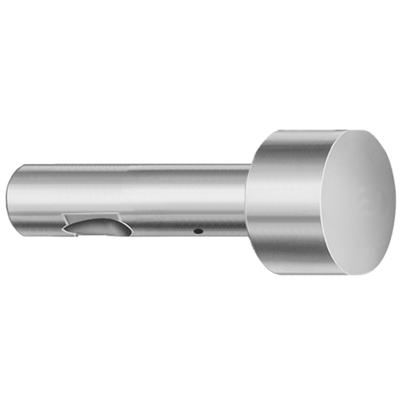
Point Larger than Shank Regular Ball Lock Punches - Light Duty, Inch
Point Larger than Shank Regular ball lock ejector punches (DAYTON) (in) deliver reliable retention in light-duty inch mold setups, helping maintain consistent ejection performance across production cycles.
- Point larger than shank design improves locating and tool engagement
- Ball lock style supports secure punch retention during cycling
- Engineered for light-duty applications where inch tooling compatibility matters
- Tip shape options (X, R, K, O, H, L, J, N, V, Y, Z) for process matching
Specifications
114 configurations available
| Tip Shape | D (Shank dia.) (in) | L (Length) (coded inch) | P Dimension (in) | W Dimension (in) | R Dimension (in) |
|---|---|---|---|---|---|
| H | 37 (0.3750") | 250 ~ 450 | 0.376 ~ 0.875 | 0.062 ~ 0.124 | - |
| H | 37 (0.3750") | 250 ~ 450 | 0.376 ~ 0.875 | 0.125 ~ 0.875 | - |
| H | 50 (0.5000") | 250 ~ 450 | 0.501 ~ 1.25 | 0.158 ~ 0.187 | - |
| H | 50 (0.5000") | 250 ~ 450 | 0.501 ~ 1.25 | 0.188 ~ 1.25 | - |
| H | 62 (0.6250") | 250 ~ 450 | 0.626 ~ 1.5 | 0.25 ~ 1.5 | - |
| H | 62 (0.6250") | 250 ~ 450 | 0.626 ~ 1.5 | 0.158 ~ 0.249 | - |
| H | 75 (0.7500") | 250 ~ 450 | 0.751 ~ 1.5 | 0.235 ~ 0.311 | - |
| H | 75 (0.7500") | 250 ~ 450 | 0.751 ~ 1.5 | 0.312 ~ 1.5 | - |
| H | 87 (0.8750") | 250 ~ 450 | 0.876 ~ 1.75 | 0.235 ~ 0.374 | - |
| H | 87 (0.8750") | 250 ~ 450 | 0.876 ~ 1.75 | 0.375 ~ 1.75 | - |
| H | 100 (1.0000") | 250 ~ 450 | 1.001 ~ 1.75 | 0.235 ~ 0.436 | - |
| H | 100 (1.0000") | 250 ~ 450 | 1.001 ~ 1.75 | 0.437 ~ 1.75 | - |
| J | 37 (0.3750") | 250 ~ 450 | 0.376 ~ 0.875 | 0.062 ~ 0.124 | - |
| J | 37 (0.3750") | 250 ~ 450 | 0.376 ~ 0.875 | 0.125 ~ 0.875 | - |
| J | 50 (0.5000") | 250 ~ 450 | 0.501 ~ 1.25 | 0.158 ~ 0.187 | - |
| J | 50 (0.5000") | 250 ~ 450 | 0.501 ~ 1.25 | 0.188 ~ 1.25 | - |
| J | 62 (0.6250") | 250 ~ 450 | 0.626 ~ 1.5 | 0.25 ~ 1.5 | - |
| J | 62 (0.6250") | 250 ~ 450 | 0.626 ~ 1.5 | 0.158 ~ 0.249 | - |
| J | 75 (0.7500") | 250 ~ 450 | 0.751 ~ 1.5 | 0.235 ~ 0.311 | - |
| J | 75 (0.7500") | 250 ~ 450 | 0.751 ~ 1.5 | 0.312 ~ 1.5 | - |
| J | 87 (0.8750") | 250 ~ 450 | 0.876 ~ 1.75 | 0.235 ~ 0.374 | - |
| J | 87 (0.8750") | 250 ~ 450 | 0.876 ~ 1.75 | 0.375 ~ 1.75 | - |
| J | 100 (1.0000") | 250 ~ 450 | 1.001 ~ 1.75 | 0.235 ~ 0.436 | - |
| J | 100 (1.0000") | 250 ~ 450 | 1.001 ~ 1.75 | 0.437 ~ 1.75 | - |
| K | 37 (0.3750") | 250 ~ 450 | 0.376 ~ 0.875 | 0.062 ~ 0.124 | 0.007 ~ 0.4375 |
| K | 37 (0.3750") | 250 ~ 450 | 0.376 ~ 0.875 | 0.125 ~ 0.875 | 0.007 ~ 0.4375 |
| K | 50 (0.5000") | 250 ~ 450 | 0.501 ~ 1.25 | 0.158 ~ 0.187 | 0.007 ~ 0.625 |
| K | 50 (0.5000") | 250 ~ 450 | 0.501 ~ 1.25 | 0.188 ~ 1.25 | 0.007 ~ 0.625 |
| K | 62 (0.6250") | 250 ~ 450 | 0.626 ~ 1.5 | 0.25 ~ 1.5 | 0.007 ~ 0.75 |
| K | 62 (0.6250") | 250 ~ 450 | 0.626 ~ 1.5 | 0.158 ~ 0.249 | 0.007 ~ 0.75 |
| K | 75 (0.7500") | 250 ~ 450 | 0.751 ~ 1.5 | 0.235 ~ 0.311 | 0.007 ~ 0.75 |
| K | 75 (0.7500") | 250 ~ 450 | 0.751 ~ 1.5 | 0.312 ~ 1.5 | 0.007 ~ 0.75 |
| K | 87 (0.8750") | 250 ~ 450 | 0.876 ~ 1.75 | 0.235 ~ 0.374 | 0.007 ~ 0.875 |
| K | 87 (0.8750") | 250 ~ 450 | 0.876 ~ 1.75 | 0.375 ~ 1.75 | 0.007 ~ 0.875 |
| K | 100 (1.0000") | 250 ~ 450 | 1.001 ~ 1.75 | 0.235 ~ 0.436 | 0.007 ~ 0.875 |
| K | 100 (1.0000") | 250 ~ 450 | 1.001 ~ 1.75 | 0.437 ~ 1.75 | 0.007 ~ 0.875 |
| L | 37 (0.3750") | 250 ~ 450 | 0.376 ~ 0.875 | 0.062 ~ 0.124 | - |
| L | 37 (0.3750") | 250 ~ 450 | 0.376 ~ 0.875 | 0.125 ~ 0.875 | - |
| L | 50 (0.5000") | 250 ~ 450 | 0.501 ~ 1.25 | 0.158 ~ 0.187 | - |
| L | 50 (0.5000") | 250 ~ 450 | 0.501 ~ 1.25 | 0.188 ~ 1.25 | - |
| L | 62 (0.6250") | 250 ~ 450 | 0.626 ~ 1.5 | 0.25 ~ 1.5 | - |
| L | 62 (0.6250") | 250 ~ 450 | 0.626 ~ 1.5 | 0.158 ~ 0.249 | - |
| L | 75 (0.7500") | 250 ~ 450 | 0.751 ~ 1.5 | 0.235 ~ 0.311 | - |
| L | 75 (0.7500") | 250 ~ 450 | 0.751 ~ 1.5 | 0.312 ~ 1.5 | - |
| L | 87 (0.8750") | 250 ~ 450 | 0.876 ~ 1.75 | 0.235 ~ 0.374 | - |
| L | 87 (0.8750") | 250 ~ 450 | 0.876 ~ 1.75 | 0.375 ~ 1.75 | - |
| L | 100 (1.0000") | 250 ~ 450 | 1.001 ~ 1.75 | 0.235 ~ 0.436 | - |
| L | 100 (1.0000") | 250 ~ 450 | 1.001 ~ 1.75 | 0.437 ~ 1.75 | - |
| N | 37 (0.3750") | 250 ~ 450 | - | 0.326 ~ 0.758 | - |
| N | 50 (0.5000") | 250 ~ 450 | - | 0.434 ~ 1.083 | - |
Product Guide
Application Scenarios+
These light-duty inch ball-lock punches are used inside injection mold tooling where stable punch retention and repeatable ejection behavior are required. In automotive connector and small sensor housing molds, the point larger than the shank improves engagement and helps maintain consistent locating during high-cycle cycling of ejector systems.
- Automotive & electronics: Use the larger tip-to-shank geometry to improve guidance and reduce misalignment effects when running compact ejector layouts.
- Medical device housings: The secure ball-lock retention supports dependable ejection timing, helping maintain part-to-part consistency under frequent starts and stops.
- Appliance and consumer components: Best suited for inch tooling setups that prioritize reliable retention in light-duty production.
With multiple tip-shape options (H, J, K, L, N, O, R, V, X, Y, Z), you can match the punch tip interface to your cavity/core features and process requirements, improving overall assembly tolerance stack behavior.
Material & Process Details+
The provided data specifies this DAYTON ball-lock punch as an inch light-duty ejector system component, but it does not include the steel grade, heat treatment state, or hardness (HRC). Therefore, material properties such as wear resistance and toughness trade-offs cannot be stated from the available specifications.
What can be confirmed from the catalog parameters is the mechanical interface intent: the ball-lock style is designed for secure punch retention during cycling, and the point larger than shank improves tool engagement. For engineers selecting steel and surface treatment for wear-critical service, match the hardness level and coating choice to the expected load, ejection pressure, and abrasive exposure rather than relying on unspecified material data.
- Heat treatment: Not specified in the provided input.
- Hardness (HRC): Not specified in the provided input.
- Wear resistance vs. toughness: Should be determined from the chosen material/heat-treatment option for your application.
Sizing & Selection Guide+
Select the correct punch by matching the shank diameter and coded length to your mold’s ejector plate and alignment features. The shank diameter D is available in inch sizes: 0.3750, 0.5000, 0.6250, 0.7500, 0.8750, and 1.0000. The fixed coded length L ranges from 250 to 450 (coded inch)—use the code that corresponds to the required protrusion and clearance for your ejector stack.
- Tip shape: Choose from H, J, K, L, N, O, R, V, X, Y, Z to match the cavity/core pocket geometry and contact interface.
- Point interface (P and W): Ensure your target engagement uses a P within 0.376–0.875, 0.501–1.25, 0.626–1.5, 0.751–1.5, 0.876–1.75, or 1.001–1.75 (as applicable) and a W within 0.062–0.867.
- Radius features (R): Verify the R dimension falls within 0.007–0.4375, 0.007–0.625, 0.007–0.75, or 0.007–0.875 depending on your selected configuration.
Ball-lock retention typically relies on dimensional fit between the punch and its retention feature; therefore, confirm that your receiving bore/seat dimensions and tolerance stack can accommodate the chosen D and the specified tip geometry without binding.
Frequently Asked Questions
Which shank diameter (D) options are available for this light-duty inch ball-lock punch series?+
How should I choose the correct coded length (L = 250–450) for an ejector stack?+
What tip shape codes (H/J/K/L/N/O/R/V/X/Y/Z) should I consider for matching cavity/core contact geometry?+
How do I verify P, W, and R dimensions against my mold’s contact pocket or ejector interface?+
Does the provided data include steel grade or hardness (HRC) for wear and toughness selection?+
Related Products


Need Custom Specifications?
Our engineering team can help with custom configurations, material selection, and volume pricing.