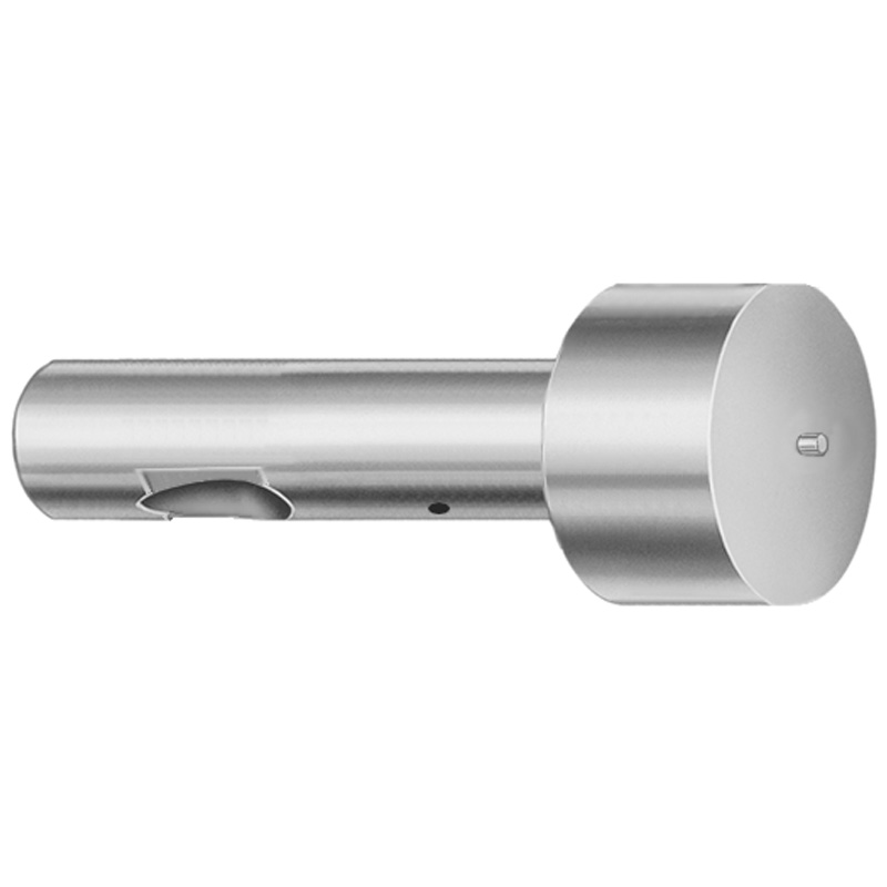
DIN Standard Hardened Steel Ball Lock Ejector Punches - Light Duty
Ball lock ejector punches - light duty (Hardened steel) from Dayton are built for efficient ejection in light-load tooling, featuring a CRN coating to enhance surface durability. The point larger than shank profile helps maintain reliable engagement and stable punch alignment during operation.
- Point larger than shank geometry improves loading stability and part contact.
- CRN coating supports abrasion resistance for long production runs.
- Precision-ground construction supports consistent assembly fit in die sets.
- Commonly used for blanking and punching applications in inch-based tooling.
Specifications
114 configurations available
| Tip Shape | D (Shank dia.) (in) | Jektole group | L (Length) (coded inch) | P Dimension (in) | W Dimension (in) | R Dimension (in) |
|---|---|---|---|---|---|---|
| H | 37 (0.3750") | J4 | 250 ~ 450 | 0.376 ~ 0.875 | 0.062 ~ 0.124 | - |
| H | 37 (0.3750") | J4 | 250 ~ 450 | 0.376 ~ 0.875 | 0.125 ~ 0.875 | - |
| H | 50 (0.5000") | J6 | 250 ~ 450 | 0.501 ~ 1.25 | 0.158 ~ 0.187 | - |
| H | 50 (0.5000") | J6 | 250 ~ 450 | 0.501 ~ 1.25 | 0.188 ~ 1.25 | - |
| H | 62 (0.6250") | J6 | 250 ~ 450 | 0.626 ~ 1.5 | 0.25 ~ 1.5 | - |
| H | 62 (0.6250") | J6 | 250 ~ 450 | 0.626 ~ 1.5 | 0.158 ~ 0.249 | - |
| H | 75 (0.7500") | J9 | 250 ~ 450 | 0.751 ~ 1.5 | 0.235 ~ 0.311 | - |
| H | 75 (0.7500") | J9 | 250 ~ 450 | 0.751 ~ 1.5 | 0.312 ~ 1.5 | - |
| H | 87 (0.8750") | J9 | 250 ~ 450 | 0.876 ~ 1.75 | 0.235 ~ 0.374 | - |
| H | 87 (0.8750") | J9 | 250 ~ 450 | 0.876 ~ 1.75 | 0.375 ~ 1.75 | - |
| H | 100 (1.0000") | J9 | 250 ~ 450 | 1.001 ~ 1.75 | 0.235 ~ 0.436 | - |
| H | 100 (1.0000") | J9 | 250 ~ 450 | 1.001 ~ 1.75 | 0.437 ~ 1.75 | - |
| J | 37 (0.3750") | J4 | 250 ~ 450 | 0.376 ~ 0.875 | 0.062 ~ 0.124 | - |
| J | 37 (0.3750") | J4 | 250 ~ 450 | 0.376 ~ 0.875 | 0.125 ~ 0.875 | - |
| J | 50 (0.5000") | J6 | 250 ~ 450 | 0.501 ~ 1.25 | 0.158 ~ 0.187 | - |
| J | 50 (0.5000") | J6 | 250 ~ 450 | 0.501 ~ 1.25 | 0.188 ~ 1.25 | - |
| J | 62 (0.6250") | J6 | 250 ~ 450 | 0.626 ~ 1.5 | 0.25 ~ 1.5 | - |
| J | 62 (0.6250") | J6 | 250 ~ 450 | 0.626 ~ 1.5 | 0.158 ~ 0.249 | - |
| J | 75 (0.7500") | J9 | 250 ~ 450 | 0.751 ~ 1.5 | 0.235 ~ 0.311 | - |
| J | 75 (0.7500") | J9 | 250 ~ 450 | 0.751 ~ 1.5 | 0.312 ~ 1.5 | - |
| J | 87 (0.8750") | J9 | 250 ~ 450 | 0.876 ~ 1.75 | 0.235 ~ 0.374 | - |
| J | 87 (0.8750") | J9 | 250 ~ 450 | 0.876 ~ 1.75 | 0.375 ~ 1.75 | - |
| J | 100 (1.0000") | J9 | 250 ~ 450 | 1.001 ~ 1.75 | 0.235 ~ 0.436 | - |
| J | 100 (1.0000") | J9 | 250 ~ 450 | 1.001 ~ 1.75 | 0.437 ~ 1.75 | - |
| K | 37 (0.3750") | J4 | 250 ~ 450 | 0.376 ~ 0.875 | 0.062 ~ 0.124 | 0.007 ~ 0.4375 |
| K | 37 (0.3750") | J4 | 250 ~ 450 | 0.376 ~ 0.875 | 0.125 ~ 0.875 | 0.007 ~ 0.4375 |
| K | 50 (0.5000") | J6 | 250 ~ 450 | 0.501 ~ 1.25 | 0.158 ~ 0.187 | 0.007 ~ 0.625 |
| K | 50 (0.5000") | J6 | 250 ~ 450 | 0.501 ~ 1.25 | 0.188 ~ 1.25 | 0.007 ~ 0.625 |
| K | 62 (0.6250") | J6 | 250 ~ 450 | 0.626 ~ 1.5 | 0.25 ~ 1.5 | 0.007 ~ 0.75 |
| K | 62 (0.6250") | J6 | 250 ~ 450 | 0.626 ~ 1.5 | 0.158 ~ 0.249 | 0.007 ~ 0.75 |
| K | 75 (0.7500") | J9 | 250 ~ 450 | 0.751 ~ 1.5 | 0.235 ~ 0.311 | 0.007 ~ 0.75 |
| K | 75 (0.7500") | J9 | 250 ~ 450 | 0.751 ~ 1.5 | 0.312 ~ 1.5 | 0.007 ~ 0.75 |
| K | 87 (0.8750") | J9 | 250 ~ 450 | 0.876 ~ 1.75 | 0.235 ~ 0.374 | 0.007 ~ 0.875 |
| K | 87 (0.8750") | J9 | 250 ~ 450 | 0.876 ~ 1.75 | 0.375 ~ 1.75 | 0.007 ~ 0.875 |
| K | 100 (1.0000") | J9 | 250 ~ 450 | 1.001 ~ 1.75 | 0.235 ~ 0.436 | 0.007 ~ 0.875 |
| K | 100 (1.0000") | J9 | 250 ~ 450 | 1.001 ~ 1.75 | 0.437 ~ 1.75 | 0.007 ~ 0.875 |
| L | 37 (0.3750") | J4 | 250 ~ 450 | 0.376 ~ 0.875 | 0.062 ~ 0.124 | - |
| L | 37 (0.3750") | J4 | 250 ~ 450 | 0.376 ~ 0.875 | 0.125 ~ 0.875 | - |
| L | 50 (0.5000") | J6 | 250 ~ 450 | 0.501 ~ 1.25 | 0.158 ~ 0.187 | - |
| L | 50 (0.5000") | J6 | 250 ~ 450 | 0.501 ~ 1.25 | 0.188 ~ 1.25 | - |
| L | 62 (0.6250") | J6 | 250 ~ 450 | 0.626 ~ 1.5 | 0.25 ~ 1.5 | - |
| L | 62 (0.6250") | J6 | 250 ~ 450 | 0.626 ~ 1.5 | 0.158 ~ 0.249 | - |
| L | 75 (0.7500") | J9 | 250 ~ 450 | 0.751 ~ 1.5 | 0.235 ~ 0.311 | - |
| L | 75 (0.7500") | J9 | 250 ~ 450 | 0.751 ~ 1.5 | 0.312 ~ 1.5 | - |
| L | 87 (0.8750") | J9 | 250 ~ 450 | 0.876 ~ 1.75 | 0.235 ~ 0.374 | - |
| L | 87 (0.8750") | J9 | 250 ~ 450 | 0.876 ~ 1.75 | 0.375 ~ 1.75 | - |
| L | 100 (1.0000") | J9 | 250 ~ 450 | 1.001 ~ 1.75 | 0.235 ~ 0.436 | - |
| L | 100 (1.0000") | J9 | 250 ~ 450 | 1.001 ~ 1.75 | 0.437 ~ 1.75 | - |
| N | 37 (0.3750") | J4 | 250 ~ 450 | - | 0.326 ~ 0.758 | - |
| N | 50 (0.5000") | J6 | 250 ~ 450 | - | 0.434 ~ 1.083 | - |
Product Guide
Application Scenarios+
This light-duty ball lock ejector punch is used inside injection mold tooling to provide positive ejection for parts that don’t require heavy stripping forces. The CRN-coated, hardened steel construction helps maintain stable punch alignment and surface integrity under repeated cycles.
- Light-load blanking and punching for inch-based tooling: the fixed-code length options (250–450) and the shank diameter range (0.375–1.000 in) support consistent fit in die sets.
- Automotive and appliance housings with moderate ejection demand: the point-larger-than-shank geometry improves loading stability and part contact so the mechanism can return reliably during production.
- Electronics enclosures and brackets requiring fine alignment: select tip shape (H, J, K, L, N, O, R, V, X, Y, Z) to match cavity/core engagement while the CRN coating improves abrasion resistance for longer run times.
Material & Process Details+
The ejector punches are manufactured from hardened steel to support precision blanking and punching in mold tooling. A CRN coating is applied to improve surface durability, targeting abrasion and wear resistance during repeated ejection cycles.
- Wear vs. toughness trade-off: hardened steel improves resistance to deformation and wear at the working interface, while the coating enhances top-surface durability without changing the core’s need for sufficient toughness.
- Heat treatment state: supplied as a hardened steel component intended for tooling environments where dimensional stability under load is required.
- Coating relevance: compared with uncoated hardened punches, the CRN layer typically provides better abrasion resistance, helping preserve fit and alignment in high-cycle production.
Sizing & Selection Guide+
Correct sizing starts by matching the shank diameter D (0.3750, 0.5000, 0.6250, 0.7500, 0.8750, 1.0000 in) to the ejector bore or guide feature in your die set. Then choose the coded length L (250–450) to achieve the required protrusion and engagement depth while maintaining safe clearance at shutoff.
- Tip shape selection: pick from H, J, K, L, N, O, R, V, X, Y, Z to align with your cavity/core contact geometry and ball lock engagement profile.
- Profile/engagement dimensions: use the available P range (0.376–0.875, 0.501–1.25, 0.626–1.5, 0.751–1.5, 0.876–1.75, 1.001–1.75 in) and W (0.062–0.867 in) to match the stop position and working footprint.
- R dimension: choose the appropriate corner radius R range (0.007–0.4375 up to 0.007–0.875 in) to control contact pressure and reduce localized wear.
Because these are precision mold components, verify mechanical fit against your assembly tolerance and consider coating thickness effects when assessing clearance.
Frequently Asked Questions
Which shank diameter D options are available for this light-duty ball lock ejector punch?+
The shank diameter D is available at 0.3750, 0.5000, 0.6250, 0.7500, 0.8750, and 1.0000 in. Select the bore/guide diameter in your die set to match the chosen D for stable alignment and repeatable ejection.
How do I choose the correct length for the required ejection stroke?+
Use the coded inch length L in the range 250–450 to set the working engagement and protrusion. Confirm that the selected length provides the required ejection contact without bottoming out during clamp.
What is the purpose of the CRN coating on these ejector punches?+
The punches use a CRN coating to improve surface wear resistance and abrasion durability during repeated ejection cycles. This helps preserve the working interface so alignment and engagement remain consistent over long production runs.
How should I select the tip shape (H/J/K/L/N/O/R/V/X/Y/Z) for die-to-core engagement?+
Choose the tip shape H, J, K, L, N, O, R, V, X, Y, Z based on your cavity/core contact geometry and the required engagement profile. The point-larger-than-shank geometry supports stable loading, but the exact tip shape should match the part contact and ball lock interface requirements.
Which engagement dimensions should I check besides D and L?+
Besides D (shank dia.) and L (length code), verify P, W, and R against the ejector bore features and contact footprint. The available ranges are P: 0.376–1.75 in (by option group), W: 0.062–0.867 in, and R: 0.007–0.4375 up to 0.007–0.875 in.
Related Products


Need Custom Specifications?
Our engineering team can help with custom configurations, material selection, and volume pricing.