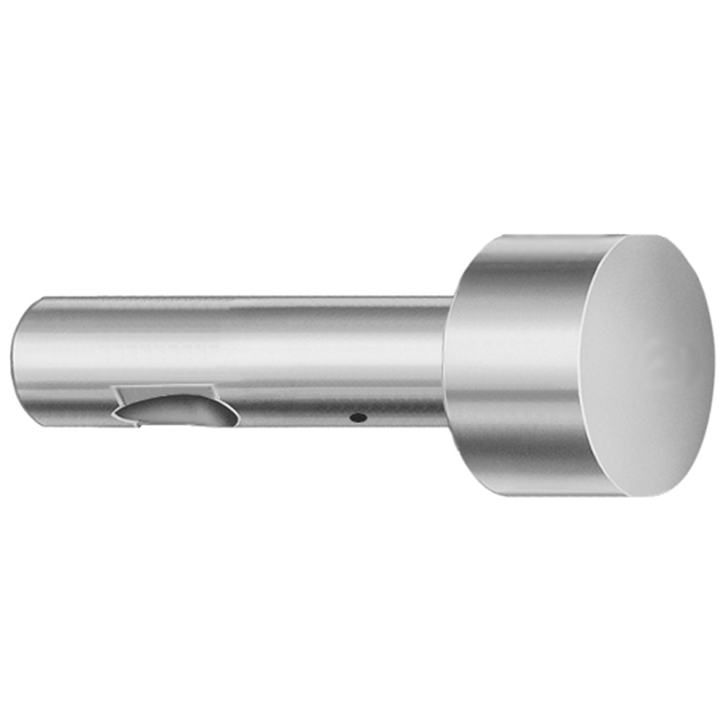
Point Larger than Shank Regular Ball Lock Punches Light Duty, Inch
Point Larger than Shank regular ball lock punches (XNT DayTiN® coating) are designed for light-duty inch tooling, delivering reliable ball-lock retention and repeatable punch performance during part ejection. The point larger than shank geometry improves engagement stability in typical press applications.
- Light-duty inch ball-lock punch design for consistent retention
- XNT DayTiN® coating supports abrasion resistance in production cycles
- Point-to-shank form maintains stable alignment for ejecting parts
- Suitable for die sets and progressive tooling requiring secure lock-up
Specifications
114 configurations available
| Tip Shape | D (Shank dia.) (in) | L (Length) (coded inch) | P Dimension (in) | W Dimension (in) | R Dimension (in) |
|---|---|---|---|---|---|
| H | 37 (0.3750") | 250 ~ 450 | 0.376 ~ 0.875 | 0.062 ~ 0.124 | - |
| H | 37 (0.3750") | 250 ~ 450 | 0.376 ~ 0.875 | 0.125 ~ 0.875 | - |
| H | 50 (0.5000") | 250 ~ 450 | 0.501 ~ 1.25 | 0.158 ~ 0.187 | - |
| H | 50 (0.5000") | 250 ~ 450 | 0.501 ~ 1.25 | 0.188 ~ 1.25 | - |
| H | 62 (0.6250") | 250 ~ 450 | 0.626 ~ 1.5 | 0.25 ~ 1.5 | - |
| H | 62 (0.6250") | 250 ~ 450 | 0.626 ~ 1.5 | 0.158 ~ 0.249 | - |
| H | 75 (0.7500") | 250 ~ 450 | 0.751 ~ 1.5 | 0.235 ~ 0.311 | - |
| H | 75 (0.7500") | 250 ~ 450 | 0.751 ~ 1.5 | 0.312 ~ 1.5 | - |
| H | 87 (0.8750") | 250 ~ 450 | 0.876 ~ 1.75 | 0.235 ~ 0.374 | - |
| H | 87 (0.8750") | 250 ~ 450 | 0.876 ~ 1.75 | 0.375 ~ 1.75 | - |
| H | 100 (1.0000") | 250 ~ 450 | 1.001 ~ 1.75 | 0.235 ~ 0.436 | - |
| H | 100 (1.0000") | 250 ~ 450 | 1.001 ~ 1.75 | 0.437 ~ 1.75 | - |
| J | 37 (0.3750") | 250 ~ 450 | 0.376 ~ 0.875 | 0.062 ~ 0.124 | - |
| J | 37 (0.3750") | 250 ~ 450 | 0.376 ~ 0.875 | 0.125 ~ 0.875 | - |
| J | 50 (0.5000") | 250 ~ 450 | 0.501 ~ 1.25 | 0.158 ~ 0.187 | - |
| J | 50 (0.5000") | 250 ~ 450 | 0.501 ~ 1.25 | 0.188 ~ 1.25 | - |
| J | 62 (0.6250") | 250 ~ 450 | 0.626 ~ 1.5 | 0.25 ~ 1.5 | - |
| J | 62 (0.6250") | 250 ~ 450 | 0.626 ~ 1.5 | 0.158 ~ 0.249 | - |
| J | 75 (0.7500") | 250 ~ 450 | 0.751 ~ 1.5 | 0.235 ~ 0.311 | - |
| J | 75 (0.7500") | 250 ~ 450 | 0.751 ~ 1.5 | 0.312 ~ 1.5 | - |
| J | 87 (0.8750") | 250 ~ 450 | 0.876 ~ 1.75 | 0.235 ~ 0.374 | - |
| J | 87 (0.8750") | 250 ~ 450 | 0.876 ~ 1.75 | 0.375 ~ 1.75 | - |
| J | 100 (1.0000") | 250 ~ 450 | 1.001 ~ 1.75 | 0.235 ~ 0.436 | - |
| J | 100 (1.0000") | 250 ~ 450 | 1.001 ~ 1.75 | 0.437 ~ 1.75 | - |
| K | 37 (0.3750") | 250 ~ 450 | 0.376 ~ 0.875 | 0.062 ~ 0.124 | 0.007 ~ 0.4375 |
| K | 37 (0.3750") | 250 ~ 450 | 0.376 ~ 0.875 | 0.125 ~ 0.875 | 0.007 ~ 0.4375 |
| K | 50 (0.5000") | 250 ~ 450 | 0.501 ~ 1.25 | 0.158 ~ 0.187 | 0.007 ~ 0.625 |
| K | 50 (0.5000") | 250 ~ 450 | 0.501 ~ 1.25 | 0.188 ~ 1.25 | 0.007 ~ 0.625 |
| K | 62 (0.6250") | 250 ~ 450 | 0.626 ~ 1.5 | 0.25 ~ 1.5 | 0.007 ~ 0.75 |
| K | 62 (0.6250") | 250 ~ 450 | 0.626 ~ 1.5 | 0.158 ~ 0.249 | 0.007 ~ 0.75 |
| K | 75 (0.7500") | 250 ~ 450 | 0.751 ~ 1.5 | 0.235 ~ 0.311 | 0.007 ~ 0.75 |
| K | 75 (0.7500") | 250 ~ 450 | 0.751 ~ 1.5 | 0.312 ~ 1.5 | 0.007 ~ 0.75 |
| K | 87 (0.8750") | 250 ~ 450 | 0.876 ~ 1.75 | 0.235 ~ 0.374 | 0.007 ~ 0.875 |
| K | 87 (0.8750") | 250 ~ 450 | 0.876 ~ 1.75 | 0.375 ~ 1.75 | 0.007 ~ 0.875 |
| K | 100 (1.0000") | 250 ~ 450 | 1.001 ~ 1.75 | 0.235 ~ 0.436 | 0.007 ~ 0.875 |
| K | 100 (1.0000") | 250 ~ 450 | 1.001 ~ 1.75 | 0.437 ~ 1.75 | 0.007 ~ 0.875 |
| L | 37 (0.3750") | 250 ~ 450 | 0.376 ~ 0.875 | 0.062 ~ 0.124 | - |
| L | 37 (0.3750") | 250 ~ 450 | 0.376 ~ 0.875 | 0.125 ~ 0.875 | - |
| L | 50 (0.5000") | 250 ~ 450 | 0.501 ~ 1.25 | 0.158 ~ 0.187 | - |
| L | 50 (0.5000") | 250 ~ 450 | 0.501 ~ 1.25 | 0.188 ~ 1.25 | - |
| L | 62 (0.6250") | 250 ~ 450 | 0.626 ~ 1.5 | 0.25 ~ 1.5 | - |
| L | 62 (0.6250") | 250 ~ 450 | 0.626 ~ 1.5 | 0.158 ~ 0.249 | - |
| L | 75 (0.7500") | 250 ~ 450 | 0.751 ~ 1.5 | 0.235 ~ 0.311 | - |
| L | 75 (0.7500") | 250 ~ 450 | 0.751 ~ 1.5 | 0.312 ~ 1.5 | - |
| L | 87 (0.8750") | 250 ~ 450 | 0.876 ~ 1.75 | 0.235 ~ 0.374 | - |
| L | 87 (0.8750") | 250 ~ 450 | 0.876 ~ 1.75 | 0.375 ~ 1.75 | - |
| L | 100 (1.0000") | 250 ~ 450 | 1.001 ~ 1.75 | 0.235 ~ 0.436 | - |
| L | 100 (1.0000") | 250 ~ 450 | 1.001 ~ 1.75 | 0.437 ~ 1.75 | - |
| N | 37 (0.3750") | 250 ~ 450 | - | 0.326 ~ 0.758 | - |
| N | 50 (0.5000") | 250 ~ 450 | - | 0.434 ~ 1.083 | - |
Product Guide
Application Scenarios+
This light-duty ball-lock punch is used in injection-molding tooling where consistent ejection and secure punch retention are required. The point larger than shank geometry improves engagement stability, helping maintain predictable lock-up during repeated cycling.
- Automotive and appliance part ejection: suited for standard die sets and ejector systems that demand reliable ball-lock retention without heavy-duty wear expectations.
- Progressive tooling for small plastic components: the stable point-to-shank form supports alignment, which helps reduce wobble and maintains consistent part release geometry.
- General-purpose mold builds in inch tool design: available tip shapes (H, J, K, L, N, O, R, V, X, Y, Z) allow matching contact profiles to part surfaces for controlled ejection.
The XNT DayTiN® coating is intended to reduce abrasion and extend usable life in production cycles where ejector elements experience friction against inserts and molded parts.
Material & Process Details+
The provided data specifies an XNT DayTiN® coating on a light-duty ball-lock punch, with no steel grade or hardness values listed. DayTiN® type coatings are typically selected to improve wear and abrasion resistance while maintaining practical toughness for repeated ejection cycles.
Because the underlying steel specification (grade), heat-treatment state (e.g., quenched & tempered, pre-hardened, nitrided), and target HRC hardness are not included in the input, those values cannot be stated accurately for this product variant.
- Coating benefit: improved resistance to rubbing wear during part ejection.
- Trade-off: coating thickness and chemistry can slightly affect dimensional response; verification is recommended when tight functional fits are required.
- Material comparison: no alternative steel grades or coating variants were provided in the specification data, so only the coating effect can be addressed.
Sizing & Selection Guide+
To select the correct punch size, match both the shank diameter (D) and the point-to-shank engagement geometry to your core/cavity ejector layout and the ball-lock pocket dimensions.
- Shank diameter (D): choose from 37 (0.3750), 50 (0.5000), 62 (0.6250), 75 (0.7500), 87 (0.8750), or 100 (1.0000) in.
- Length (L, coded inch): confirm the required stroke/stack height using L in the range 250–450.
- P dimension: use the matching range for your style: 0.376–0.875, 0.501–1.25, 0.626–1.5, 0.751–1.5, 0.876–1.75, or 1.001–1.75 in.
- W and R: set the profile with W = 0.062–0.867 in and R = 0.007–0.4375 / 0.007–0.625 / 0.007–0.75 / 0.007–0.875 in depending on the selected configuration.
Plan for functional fit by verifying the selected D and point geometry against your ejector plate hole and ball-lock receiver dimensions; tolerance requirements are not provided, so confirm with your mold drawing standards and supplier datasheet.
Frequently Asked Questions
Which shank diameter (D) options are available for this light-duty inch ball-lock punch?+
The available D (shank diameter) values are 37 (0.3750), 50 (0.5000), 62 (0.6250), 75 (0.7500), 87 (0.8750), and 100 (1.0000) inches.
Choose the D that matches your ejector system hole size and ball-lock receiver bore.
How do I select the correct coded length L for the required ejector travel?+
The specification provides L (coded inch) as 250–450.
Select the value that fits your mold stack-up and required ejector stroke. If your drawing uses physical length rather than coded inches, convert using your internal standard and verify end-to-end fit.
What point profile ranges (P, W, R) should be matched to the part ejection geometry?+
Point profile dimensions are given as configurable ranges: P = 0.376–0.875, 0.501–1.25, 0.626–1.5, 0.751–1.5, 0.876–1.75, or 1.001–1.75 in; W = 0.062–0.867 in; and R = 0.007–0.4375, 0.007–0.625, 0.007–0.75, or 0.007–0.875 in.
Use these to align the point-to-shank engagement and contact radius with your ejector contact face and molded part features.
Does the XNT DayTiN® coating change sizing or fit for ball-lock retention?+
The input confirms an XNT DayTiN® coating but does not provide coating thickness or tolerance impacts.
For tight functional fits, verify the coated dimensions against your mold drawing requirements and ball-lock receiver clearances. Plan for any dimensional response caused by coating during qualification builds.
What tip shapes are available for this punch variant?+
Tip shape options are listed as H, J, K, L, N, O, R, V, X, Y, Z.
Select the tip shape that best matches the molded part surface geometry and the required ejection contact profile while keeping stable point-to-shank engagement.
Related Products


Need Custom Specifications?
Our engineering team can help with custom configurations, material selection, and volume pricing.