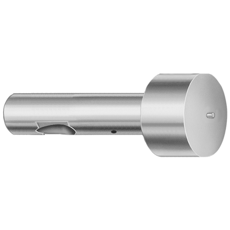
Steel Ball Lock Ejector Punches Light Duty, Inch, XNT DayTiN® Coating
Ball Lock ejector punches light duty, inch, XNT DayTiN® coating (Steel) are precision tool steels punches for ball-lock ejection in light-duty inch-based mold builds. The larger point geometry helps ensure reliable contact and stable positioning during operation.
- Ball-lock point design supports consistent ejection in mold cycles
- XNT DayTiN® coating improves wear and surface durability
- Controlled production for stable fit in punch-and-retainer assemblies
- Designed for die/mold tooling using light-duty inch standards
Specifications
114 configurations available
| Tip Shape | D (Shank dia.) (in) | Jektole group | L (Length) (coded inch) | P Dimension (in) | W Dimension (in) | R Dimension (in) |
|---|---|---|---|---|---|---|
| H | 37 (0.3750") | J4 | 250 ~ 450 | 0.376 ~ 0.875 | 0.062 ~ 0.124 | - |
| H | 37 (0.3750") | J4 | 250 ~ 450 | 0.376 ~ 0.875 | 0.125 ~ 0.875 | - |
| H | 50 (0.5000") | J6 | 250 ~ 450 | 0.501 ~ 1.25 | 0.158 ~ 0.187 | - |
| H | 50 (0.5000") | J6 | 250 ~ 450 | 0.501 ~ 1.25 | 0.188 ~ 1.25 | - |
| H | 62 (0.6250") | J6 | 250 ~ 450 | 0.626 ~ 1.5 | 0.25 ~ 1.5 | - |
| H | 62 (0.6250") | J6 | 250 ~ 450 | 0.626 ~ 1.5 | 0.158 ~ 0.249 | - |
| H | 75 (0.7500") | J9 | 250 ~ 450 | 0.751 ~ 1.5 | 0.235 ~ 0.311 | - |
| H | 75 (0.7500") | J9 | 250 ~ 450 | 0.751 ~ 1.5 | 0.312 ~ 1.5 | - |
| H | 87 (0.8750") | J9 | 250 ~ 450 | 0.876 ~ 1.75 | 0.235 ~ 0.374 | - |
| H | 87 (0.8750") | J9 | 250 ~ 450 | 0.876 ~ 1.75 | 0.375 ~ 1.75 | - |
| H | 100 (1.0000") | J9 | 250 ~ 450 | 1.001 ~ 1.75 | 0.235 ~ 0.436 | - |
| H | 100 (1.0000") | J9 | 250 ~ 450 | 1.001 ~ 1.75 | 0.437 ~ 1.75 | - |
| J | 37 (0.3750") | J4 | 250 ~ 450 | 0.376 ~ 0.875 | 0.062 ~ 0.124 | - |
| J | 37 (0.3750") | J4 | 250 ~ 450 | 0.376 ~ 0.875 | 0.125 ~ 0.875 | - |
| J | 50 (0.5000") | J6 | 250 ~ 450 | 0.501 ~ 1.25 | 0.158 ~ 0.187 | - |
| J | 50 (0.5000") | J6 | 250 ~ 450 | 0.501 ~ 1.25 | 0.188 ~ 1.25 | - |
| J | 62 (0.6250") | J6 | 250 ~ 450 | 0.626 ~ 1.5 | 0.25 ~ 1.5 | - |
| J | 62 (0.6250") | J6 | 250 ~ 450 | 0.626 ~ 1.5 | 0.158 ~ 0.249 | - |
| J | 75 (0.7500") | J9 | 250 ~ 450 | 0.751 ~ 1.5 | 0.235 ~ 0.311 | - |
| J | 75 (0.7500") | J9 | 250 ~ 450 | 0.751 ~ 1.5 | 0.312 ~ 1.5 | - |
| J | 87 (0.8750") | J9 | 250 ~ 450 | 0.876 ~ 1.75 | 0.235 ~ 0.374 | - |
| J | 87 (0.8750") | J9 | 250 ~ 450 | 0.876 ~ 1.75 | 0.375 ~ 1.75 | - |
| J | 100 (1.0000") | J9 | 250 ~ 450 | 1.001 ~ 1.75 | 0.235 ~ 0.436 | - |
| J | 100 (1.0000") | J9 | 250 ~ 450 | 1.001 ~ 1.75 | 0.437 ~ 1.75 | - |
| K | 37 (0.3750") | J4 | 250 ~ 450 | 0.376 ~ 0.875 | 0.062 ~ 0.124 | 0.007 ~ 0.4375 |
| K | 37 (0.3750") | J4 | 250 ~ 450 | 0.376 ~ 0.875 | 0.125 ~ 0.875 | 0.007 ~ 0.4375 |
| K | 50 (0.5000") | J6 | 250 ~ 450 | 0.501 ~ 1.25 | 0.158 ~ 0.187 | 0.007 ~ 0.625 |
| K | 50 (0.5000") | J6 | 250 ~ 450 | 0.501 ~ 1.25 | 0.188 ~ 1.25 | 0.007 ~ 0.625 |
| K | 62 (0.6250") | J6 | 250 ~ 450 | 0.626 ~ 1.5 | 0.25 ~ 1.5 | 0.007 ~ 0.75 |
| K | 62 (0.6250") | J6 | 250 ~ 450 | 0.626 ~ 1.5 | 0.158 ~ 0.249 | 0.007 ~ 0.75 |
| K | 75 (0.7500") | J9 | 250 ~ 450 | 0.751 ~ 1.5 | 0.235 ~ 0.311 | 0.007 ~ 0.75 |
| K | 75 (0.7500") | J9 | 250 ~ 450 | 0.751 ~ 1.5 | 0.312 ~ 1.5 | 0.007 ~ 0.75 |
| K | 87 (0.8750") | J9 | 250 ~ 450 | 0.876 ~ 1.75 | 0.235 ~ 0.374 | 0.007 ~ 0.875 |
| K | 87 (0.8750") | J9 | 250 ~ 450 | 0.876 ~ 1.75 | 0.375 ~ 1.75 | 0.007 ~ 0.875 |
| K | 100 (1.0000") | J9 | 250 ~ 450 | 1.001 ~ 1.75 | 0.235 ~ 0.436 | 0.007 ~ 0.875 |
| K | 100 (1.0000") | J9 | 250 ~ 450 | 1.001 ~ 1.75 | 0.437 ~ 1.75 | 0.007 ~ 0.875 |
| L | 37 (0.3750") | J4 | 250 ~ 450 | 0.376 ~ 0.875 | 0.062 ~ 0.124 | - |
| L | 37 (0.3750") | J4 | 250 ~ 450 | 0.376 ~ 0.875 | 0.125 ~ 0.875 | - |
| L | 50 (0.5000") | J6 | 250 ~ 450 | 0.501 ~ 1.25 | 0.158 ~ 0.187 | - |
| L | 50 (0.5000") | J6 | 250 ~ 450 | 0.501 ~ 1.25 | 0.188 ~ 1.25 | - |
| L | 62 (0.6250") | J6 | 250 ~ 450 | 0.626 ~ 1.5 | 0.25 ~ 1.5 | - |
| L | 62 (0.6250") | J6 | 250 ~ 450 | 0.626 ~ 1.5 | 0.158 ~ 0.249 | - |
| L | 75 (0.7500") | J9 | 250 ~ 450 | 0.751 ~ 1.5 | 0.235 ~ 0.311 | - |
| L | 75 (0.7500") | J9 | 250 ~ 450 | 0.751 ~ 1.5 | 0.312 ~ 1.5 | - |
| L | 87 (0.8750") | J9 | 250 ~ 450 | 0.876 ~ 1.75 | 0.235 ~ 0.374 | - |
| L | 87 (0.8750") | J9 | 250 ~ 450 | 0.876 ~ 1.75 | 0.375 ~ 1.75 | - |
| L | 100 (1.0000") | J9 | 250 ~ 450 | 1.001 ~ 1.75 | 0.235 ~ 0.436 | - |
| L | 100 (1.0000") | J9 | 250 ~ 450 | 1.001 ~ 1.75 | 0.437 ~ 1.75 | - |
| N | 37 (0.3750") | J4 | 250 ~ 450 | - | 0.326 ~ 0.758 | - |
| N | 50 (0.5000") | J6 | 250 ~ 450 | - | 0.434 ~ 1.083 | - |
Product Guide
Application Scenarios+
These light-duty ball lock ejector punches are used in injection mold tooling where the ejector system must provide stable positioning and repeatable, controlled ejection. The ball-lock point geometry is especially effective in mold bases that rely on punch-and-retainer assemblies to prevent punch drift during cycling.
- Automotive connector and small housing molds: Suitable for inch-standard components requiring consistent ejector contact. The larger point geometry helps maintain alignment while operating at moderate loads.
- Appliance and consumer product enclosures: Often require reliable ejection with limited space. The configurable shank diameter range and coded lengths (L = 250–450) support compact ejector layouts.
- Precision electronics housings: Beneficial when surface durability against wear is needed. The XNT DayTiN® coating improves wear resistance in high-cycle ejection.
Overall, this variant pairs the ball-lock contact design with an XNT DayTiN® surface treatment to improve wear behavior in light-duty, inch-based mold builds.
Material & Process Details+
The punch is specified as Steel with an XNT DayTiN® coating intended to improve surface durability in ejector service. While the exact steel grade and heat-treatment cycle are not provided in the data, the manufacturing approach for light-duty ejector punches typically uses precision tool-steel stock and a controlled finishing process to maintain fit with the retainer.
- Coating (XNT DayTiN®): Enhances wear resistance at the contact surfaces, helping resist abrasion during repeated ejection cycles.
- Hardness & toughness trade-off: In ejector applications, higher surface hardness improves wear life, but over-hardening can reduce toughness. The coating provides a surface-focused wear improvement while keeping the underlying steel suitable for light-duty loading.
- Heat treatment state: Not specified; selection is typically aligned to achieve stable core toughness and dimensional control before coating.
If you require a specific HRC target or a defined heat-treatment state, confirm the steel grade and processing route with your Axiom Molds technical representative.
Sizing & Selection Guide+
Selection starts by matching the ejector punch to the inch-based mold retainer and cavity/core spacing requirements. Use the provided dimension ranges to select the correct shank diameter and the coded length for your layout.
- Shank diameter (D, in): Choose from 0.3750 (37), 0.5000 (50), 0.6250 (62), 0.7500 (75), 0.8750 (87), or 1.0000 (100).
- Length (L, coded inch): Select L in the range 250 to 450 to achieve the required ejection travel and clearance.
- Tip geometry: Confirm the Tip Shape code (H, J, K, L, N, O, R, V, X, Y, Z) that matches your ball-lock interface design.
- P and W dimensions: Use the P range and W range to verify contact and engagement with the retainer; P is listed as 0.376–0.875, 0.501–1.25, 0.626–1.5, 0.751–1.5, 0.876–1.75, 1.001–1.75, and W is 0.062–0.867.
- R dimension: Verify radius using the provided R ranges (0.007–0.4375 up to 0.007–0.875 depending on variant).
Because tolerances are not specified in the data, ensure your retainer/punch interface tolerances are validated in your assembly drawings before final approval.
Frequently Asked Questions
Which shank diameter (D) options are available for the inch light-duty ball lock ejector punches?+
Available shank diameters are 0.3750 (37), 0.5000 (50), 0.6250 (62), 0.7500 (75), 0.8750 (87), and 1.0000 (100) in. Pick the D size that matches the punch-and-retainer bore and alignment features in your mold assembly.
How do I select the correct coded length (L) for the punch-to-retainer engagement?+
The coded length L is specified as 250 to 450. Choose L to achieve the required ejection travel while maintaining proper clearance to the cavity/core and ensuring full engagement within the retainer during cycling.
What tip shapes and jektole groups are supported by this series?+
The product supports Tip Shape codes: H, J, K, L, N, O, R, V, X, Y, Z. The jektole group is provided as J4, J6, J9; use these identifiers to match your specific ball-lock interface geometry.
How do P, W, and R dimensions affect fit in the punch-and-retainer assembly?+
The interface is controlled by P (0.376–1.75 in by variant), W (0.062–0.867 in), and R (0.007–0.4375 up to 0.007–0.875 depending on the configuration). Confirm these values against your retainer design so the ball-lock point engages consistently without excessive clearance.
What does the XNT DayTiN® coating contribute to ejector performance in light-duty molds?+
This series specifies an XNT DayTiN® coating to enhance surface wear durability at the ejector contact areas. It is intended to improve resistance to abrasion during repeated ejection cycles while maintaining reliable punch-and-retainer function for light-duty inch builds.
Related Products


Need Custom Specifications?
Our engineering team can help with custom configurations, material selection, and volume pricing.