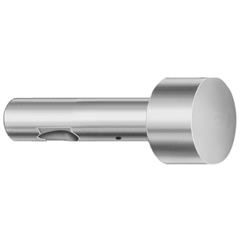
Ball Lock Ejector Punches - Light Duty, Inch (XNAP Coating)
Ball Lock Ejector Punches - Light Duty, Inch (XNAP coating) are designed for dependable part ejection in precision tooling. The enlarged ball lock point improves retention and enables consistent punch positioning during repeated cycles.
- Ball lock point larger than shank helps maintain secure assembly during ejection
- XNAP coating supports wear resistance for extended run performance
- Tip geometry options (e.g., X, R, K, O) allow fit to die layouts
- Inch light-duty format suits maintenance-friendly die replacement and tooling upkeep
Specifications
114 configurations available
| Tip Shape | D (Shank dia.) (in) | L (Length) (coded inch) | P Dimension (in) | W Dimension (in) | R Dimension (in) |
|---|---|---|---|---|---|
| H | 37 (0.3750") | 250 ~ 450 | 0.376 ~ 0.875 | 0.062 ~ 0.124 | - |
| H | 37 (0.3750") | 250 ~ 450 | 0.376 ~ 0.875 | 0.125 ~ 0.875 | - |
| H | 50 (0.5000") | 250 ~ 450 | 0.501 ~ 1.25 | 0.158 ~ 0.187 | - |
| H | 50 (0.5000") | 250 ~ 450 | 0.501 ~ 1.25 | 0.188 ~ 1.25 | - |
| H | 62 (0.6250") | 250 ~ 450 | 0.626 ~ 1.5 | 0.25 ~ 1.5 | - |
| H | 62 (0.6250") | 250 ~ 450 | 0.626 ~ 1.5 | 0.158 ~ 0.249 | - |
| H | 75 (0.7500") | 250 ~ 450 | 0.751 ~ 1.5 | 0.235 ~ 0.311 | - |
| H | 75 (0.7500") | 250 ~ 450 | 0.751 ~ 1.5 | 0.312 ~ 1.5 | - |
| H | 87 (0.8750") | 250 ~ 450 | 0.876 ~ 1.75 | 0.235 ~ 0.374 | - |
| H | 87 (0.8750") | 250 ~ 450 | 0.876 ~ 1.75 | 0.375 ~ 1.75 | - |
| H | 100 (1.0000") | 250 ~ 450 | 1.001 ~ 1.75 | 0.235 ~ 0.436 | - |
| H | 100 (1.0000") | 250 ~ 450 | 1.001 ~ 1.75 | 0.437 ~ 1.75 | - |
| J | 37 (0.3750") | 250 ~ 450 | 0.376 ~ 0.875 | 0.062 ~ 0.124 | - |
| J | 37 (0.3750") | 250 ~ 450 | 0.376 ~ 0.875 | 0.125 ~ 0.875 | - |
| J | 50 (0.5000") | 250 ~ 450 | 0.501 ~ 1.25 | 0.158 ~ 0.187 | - |
| J | 50 (0.5000") | 250 ~ 450 | 0.501 ~ 1.25 | 0.188 ~ 1.25 | - |
| J | 62 (0.6250") | 250 ~ 450 | 0.626 ~ 1.5 | 0.25 ~ 1.5 | - |
| J | 62 (0.6250") | 250 ~ 450 | 0.626 ~ 1.5 | 0.158 ~ 0.249 | - |
| J | 75 (0.7500") | 250 ~ 450 | 0.751 ~ 1.5 | 0.235 ~ 0.311 | - |
| J | 75 (0.7500") | 250 ~ 450 | 0.751 ~ 1.5 | 0.312 ~ 1.5 | - |
| J | 87 (0.8750") | 250 ~ 450 | 0.876 ~ 1.75 | 0.235 ~ 0.374 | - |
| J | 87 (0.8750") | 250 ~ 450 | 0.876 ~ 1.75 | 0.375 ~ 1.75 | - |
| J | 100 (1.0000") | 250 ~ 450 | 1.001 ~ 1.75 | 0.235 ~ 0.436 | - |
| J | 100 (1.0000") | 250 ~ 450 | 1.001 ~ 1.75 | 0.437 ~ 1.75 | - |
| K | 37 (0.3750") | 250 ~ 450 | 0.376 ~ 0.875 | 0.062 ~ 0.124 | 0.007 ~ 0.4375 |
| K | 37 (0.3750") | 250 ~ 450 | 0.376 ~ 0.875 | 0.125 ~ 0.875 | 0.007 ~ 0.4375 |
| K | 50 (0.5000") | 250 ~ 450 | 0.501 ~ 1.25 | 0.158 ~ 0.187 | 0.007 ~ 0.625 |
| K | 50 (0.5000") | 250 ~ 450 | 0.501 ~ 1.25 | 0.188 ~ 1.25 | 0.007 ~ 0.625 |
| K | 62 (0.6250") | 250 ~ 450 | 0.626 ~ 1.5 | 0.25 ~ 1.5 | 0.007 ~ 0.75 |
| K | 62 (0.6250") | 250 ~ 450 | 0.626 ~ 1.5 | 0.158 ~ 0.249 | 0.007 ~ 0.75 |
| K | 75 (0.7500") | 250 ~ 450 | 0.751 ~ 1.5 | 0.235 ~ 0.311 | 0.007 ~ 0.75 |
| K | 75 (0.7500") | 250 ~ 450 | 0.751 ~ 1.5 | 0.312 ~ 1.5 | 0.007 ~ 0.75 |
| K | 87 (0.8750") | 250 ~ 450 | 0.876 ~ 1.75 | 0.235 ~ 0.374 | 0.007 ~ 0.875 |
| K | 87 (0.8750") | 250 ~ 450 | 0.876 ~ 1.75 | 0.375 ~ 1.75 | 0.007 ~ 0.875 |
| K | 100 (1.0000") | 250 ~ 450 | 1.001 ~ 1.75 | 0.235 ~ 0.436 | 0.007 ~ 0.875 |
| K | 100 (1.0000") | 250 ~ 450 | 1.001 ~ 1.75 | 0.437 ~ 1.75 | 0.007 ~ 0.875 |
| L | 37 (0.3750") | 250 ~ 450 | 0.376 ~ 0.875 | 0.062 ~ 0.124 | - |
| L | 37 (0.3750") | 250 ~ 450 | 0.376 ~ 0.875 | 0.125 ~ 0.875 | - |
| L | 50 (0.5000") | 250 ~ 450 | 0.501 ~ 1.25 | 0.158 ~ 0.187 | - |
| L | 50 (0.5000") | 250 ~ 450 | 0.501 ~ 1.25 | 0.188 ~ 1.25 | - |
| L | 62 (0.6250") | 250 ~ 450 | 0.626 ~ 1.5 | 0.25 ~ 1.5 | - |
| L | 62 (0.6250") | 250 ~ 450 | 0.626 ~ 1.5 | 0.158 ~ 0.249 | - |
| L | 75 (0.7500") | 250 ~ 450 | 0.751 ~ 1.5 | 0.235 ~ 0.311 | - |
| L | 75 (0.7500") | 250 ~ 450 | 0.751 ~ 1.5 | 0.312 ~ 1.5 | - |
| L | 87 (0.8750") | 250 ~ 450 | 0.876 ~ 1.75 | 0.235 ~ 0.374 | - |
| L | 87 (0.8750") | 250 ~ 450 | 0.876 ~ 1.75 | 0.375 ~ 1.75 | - |
| L | 100 (1.0000") | 250 ~ 450 | 1.001 ~ 1.75 | 0.235 ~ 0.436 | - |
| L | 100 (1.0000") | 250 ~ 450 | 1.001 ~ 1.75 | 0.437 ~ 1.75 | - |
| N | 37 (0.3750") | 250 ~ 450 | - | 0.326 ~ 0.758 | - |
| N | 50 (0.5000") | 250 ~ 450 | - | 0.434 ~ 1.083 | - |
Product Guide
Application Scenarios+
Ball lock ejector punches are used inside injection mold tooling to push formed parts out of the cavity with controlled force. This light-duty, inch configuration is commonly applied in tool and die builds where frequent maintenance and part-to-part changeovers are expected.
- Automotive and appliance housings: Ideal when the ejector travel must be consistent and the punch must stay positively seated during repeated cycles. The enlarged ball-lock point (larger than shank) improves retention and helps maintain stable punch positioning.
- Electronics and connector subcomponents: Suited for compact mold stacks where precise alignment and predictable ejection reduce risk of scuffing or mis-mating ejector features.
- Medical device housings: Beneficial for precision tooling that benefits from stable assembly and wear support from the XNAP coating over longer run periods.
The XNAP coating supports wear resistance, helping preserve geometry and ejection repeatability in light-duty applications.
Material & Process Details+
The provided specifications identify this as a DAYTON light-duty ball lock ejector punch with XNAP coating, but no underlying base steel grade is listed in the supplied data. Therefore, exact HRC values, quench-and-temper parameters, and heat treatment state of the core material cannot be confirmed from the input.
What can be stated from the product configuration is that the XNAP coating is used to improve wear resistance at the working tip and sliding interfaces, supporting stable performance across repeated ejection cycles. For mold builders, this coating is typically selected when maintaining punch dimensional stability matters more than maximizing toughness for heavy shock loads.
- Wear resistance vs. toughness trade-off: Coating-enhanced variants generally prioritize surface durability; severe impact or very aggressive ejection loads may require heavier-duty punch designs with different base material and heat treatment.
- Material availability comparison: No alternate steel grades are specified here, so direct comparisons cannot be made.
Sizing & Selection Guide+
To select the correct ball lock ejector punch, match the shank diameter D to the die or stripper plate pocket size. This punch series offers D (in) in the ranges: 0.3750 (37), 0.5000 (50), 0.6250 (62), 0.7500 (75), 0.8750 (87), and 1.0000 (100).
- Length (L): Choose the coded L range 250 ~ 450 to cover the required ejector stroke and engagement depth in your tool stack.
- Tip/pocket engagement (P and W): Confirm the P (in) range (e.g., 0.376–0.875, 0.501–1.25, 0.626–1.5, 0.751–1.5, 0.876–1.75, 1.001–1.75) and the W (in) range 0.062 ~ 0.867 against your die cavity/core layout and guide clearances.
- Geometry (R and Tip Shape): Select Tip Shape (H, J, K, L, N, O, R, V, X, Y, Z) and corresponding R (in) from the available ranges (e.g., 0.007–0.4375 up to 0.007–0.875) to ensure proper contact profile.
Because tolerance/fit values are not provided in the input data, verify your mold drawings’ clearance requirements for the ejector pocket and the ball-lock retention area before finalizing.
Frequently Asked Questions
Which shank diameter (D) options are available for this inch light-duty ball lock ejector punch series?+
This series lists D (shank dia.) in-inch options of 0.3750 (37), 0.5000 (50), 0.6250 (62), 0.7500 (75), 0.8750 (87), and 1.0000 (100).
Select the D value that matches your ejector guide/pocket diameter for correct seating and stable ejection.
How does the enlarged ball-lock point (larger than shank) affect punch retention in the mold?+
The design feature states that the ball lock point is larger than the shank, which helps maintain a secure assembly during ejection.
In practice, this improves retention and supports consistent punch positioning through repeated cycles, reducing the risk of misalignment in the ejection path.
What tip shape and radius (R) choices can be configured for different die contact profiles?+
Available Tip Shape codes include H, J, K, L, N, O, R, V, X, Y, Z.
The R (in) option ranges are provided in multiple bands (e.g., 0.007–0.4375 up to 0.007–0.875 depending on the configuration).
What length range (L) should be used to ensure adequate ejector engagement in the tool stack?+
The fixed coded Length (L) range is 250 ~ 450.
Choose L based on your required ejection travel and the engagement depth needed so the ball-lock point can hold position without bottoming in the ejector guide.
How do I select P and W dimensions for alignment with my cavity/core layout?+
This series provides P (in) ranges such as 0.376 ~ 0.875, 0.501 ~ 1.25, 0.626 ~ 1.5, 0.751 ~ 1.5, 0.876 ~ 1.75, and 1.001 ~ 1.75.
W (in) is listed as 0.062 ~ 0.867.
Match these to your die layout and any contact width/clearance requirements so the ejector tip geometry achieves the intended contact without interference.
Related Products


Need Custom Specifications?
Our engineering team can help with custom configurations, material selection, and volume pricing.