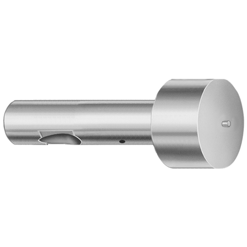
Ball Lock Ejector Punches - Light Duty, Inch
Ball Lock Ejector Punches - Light Duty, Inch (XCN coating) are designed for reliable ejection with a secure ball-lock point that helps maintain punch alignment through repeated cycles.
- Ball-lock point for consistent retention and controlled ejection
- XCN coating supports wear resistance in light-duty stamping
- Inch format construction for straightforward setup in American tooling
- Suitable for punch and die assemblies requiring precise, repeatable actuation
Specifications
114 configurations available
| Tip Shape | D (Shank dia.) (in) | Jektole group | L (Length) (coded inch) | P Dimension (in) | W Dimension (in) | R Dimension (in) |
|---|---|---|---|---|---|---|
| H | 37 (0.3750") | J4 | 250 ~ 450 | 0.376 ~ 0.875 | 0.062 ~ 0.124 | - |
| H | 37 (0.3750") | J4 | 250 ~ 450 | 0.376 ~ 0.875 | 0.125 ~ 0.875 | - |
| H | 50 (0.5000") | J6 | 250 ~ 450 | 0.501 ~ 1.25 | 0.158 ~ 0.187 | - |
| H | 50 (0.5000") | J6 | 250 ~ 450 | 0.501 ~ 1.25 | 0.188 ~ 1.25 | - |
| H | 62 (0.6250") | J6 | 250 ~ 450 | 0.626 ~ 1.5 | 0.25 ~ 1.5 | - |
| H | 62 (0.6250") | J6 | 250 ~ 450 | 0.626 ~ 1.5 | 0.158 ~ 0.249 | - |
| H | 75 (0.7500") | J9 | 250 ~ 450 | 0.751 ~ 1.5 | 0.235 ~ 0.311 | - |
| H | 75 (0.7500") | J9 | 250 ~ 450 | 0.751 ~ 1.5 | 0.312 ~ 1.5 | - |
| H | 87 (0.8750") | J9 | 250 ~ 450 | 0.876 ~ 1.75 | 0.235 ~ 0.374 | - |
| H | 87 (0.8750") | J9 | 250 ~ 450 | 0.876 ~ 1.75 | 0.375 ~ 1.75 | - |
| H | 100 (1.0000") | J9 | 250 ~ 450 | 1.001 ~ 1.75 | 0.235 ~ 0.436 | - |
| H | 100 (1.0000") | J9 | 250 ~ 450 | 1.001 ~ 1.75 | 0.437 ~ 1.75 | - |
| J | 37 (0.3750") | J4 | 250 ~ 450 | 0.376 ~ 0.875 | 0.062 ~ 0.124 | - |
| J | 37 (0.3750") | J4 | 250 ~ 450 | 0.376 ~ 0.875 | 0.125 ~ 0.875 | - |
| J | 50 (0.5000") | J6 | 250 ~ 450 | 0.501 ~ 1.25 | 0.158 ~ 0.187 | - |
| J | 50 (0.5000") | J6 | 250 ~ 450 | 0.501 ~ 1.25 | 0.188 ~ 1.25 | - |
| J | 62 (0.6250") | J6 | 250 ~ 450 | 0.626 ~ 1.5 | 0.25 ~ 1.5 | - |
| J | 62 (0.6250") | J6 | 250 ~ 450 | 0.626 ~ 1.5 | 0.158 ~ 0.249 | - |
| J | 75 (0.7500") | J9 | 250 ~ 450 | 0.751 ~ 1.5 | 0.235 ~ 0.311 | - |
| J | 75 (0.7500") | J9 | 250 ~ 450 | 0.751 ~ 1.5 | 0.312 ~ 1.5 | - |
| J | 87 (0.8750") | J9 | 250 ~ 450 | 0.876 ~ 1.75 | 0.235 ~ 0.374 | - |
| J | 87 (0.8750") | J9 | 250 ~ 450 | 0.876 ~ 1.75 | 0.375 ~ 1.75 | - |
| J | 100 (1.0000") | J9 | 250 ~ 450 | 1.001 ~ 1.75 | 0.235 ~ 0.436 | - |
| J | 100 (1.0000") | J9 | 250 ~ 450 | 1.001 ~ 1.75 | 0.437 ~ 1.75 | - |
| K | 37 (0.3750") | J4 | 250 ~ 450 | 0.376 ~ 0.875 | 0.062 ~ 0.124 | 0.007 ~ 0.4375 |
| K | 37 (0.3750") | J4 | 250 ~ 450 | 0.376 ~ 0.875 | 0.125 ~ 0.875 | 0.007 ~ 0.4375 |
| K | 50 (0.5000") | J6 | 250 ~ 450 | 0.501 ~ 1.25 | 0.158 ~ 0.187 | 0.007 ~ 0.625 |
| K | 50 (0.5000") | J6 | 250 ~ 450 | 0.501 ~ 1.25 | 0.188 ~ 1.25 | 0.007 ~ 0.625 |
| K | 62 (0.6250") | J6 | 250 ~ 450 | 0.626 ~ 1.5 | 0.25 ~ 1.5 | 0.007 ~ 0.75 |
| K | 62 (0.6250") | J6 | 250 ~ 450 | 0.626 ~ 1.5 | 0.158 ~ 0.249 | 0.007 ~ 0.75 |
| K | 75 (0.7500") | J9 | 250 ~ 450 | 0.751 ~ 1.5 | 0.235 ~ 0.311 | 0.007 ~ 0.75 |
| K | 75 (0.7500") | J9 | 250 ~ 450 | 0.751 ~ 1.5 | 0.312 ~ 1.5 | 0.007 ~ 0.75 |
| K | 87 (0.8750") | J9 | 250 ~ 450 | 0.876 ~ 1.75 | 0.235 ~ 0.374 | 0.007 ~ 0.875 |
| K | 87 (0.8750") | J9 | 250 ~ 450 | 0.876 ~ 1.75 | 0.375 ~ 1.75 | 0.007 ~ 0.875 |
| K | 100 (1.0000") | J9 | 250 ~ 450 | 1.001 ~ 1.75 | 0.235 ~ 0.436 | 0.007 ~ 0.875 |
| K | 100 (1.0000") | J9 | 250 ~ 450 | 1.001 ~ 1.75 | 0.437 ~ 1.75 | 0.007 ~ 0.875 |
| L | 37 (0.3750") | J4 | 250 ~ 450 | 0.376 ~ 0.875 | 0.062 ~ 0.124 | - |
| L | 37 (0.3750") | J4 | 250 ~ 450 | 0.376 ~ 0.875 | 0.125 ~ 0.875 | - |
| L | 50 (0.5000") | J6 | 250 ~ 450 | 0.501 ~ 1.25 | 0.158 ~ 0.187 | - |
| L | 50 (0.5000") | J6 | 250 ~ 450 | 0.501 ~ 1.25 | 0.188 ~ 1.25 | - |
| L | 62 (0.6250") | J6 | 250 ~ 450 | 0.626 ~ 1.5 | 0.25 ~ 1.5 | - |
| L | 62 (0.6250") | J6 | 250 ~ 450 | 0.626 ~ 1.5 | 0.158 ~ 0.249 | - |
| L | 75 (0.7500") | J9 | 250 ~ 450 | 0.751 ~ 1.5 | 0.235 ~ 0.311 | - |
| L | 75 (0.7500") | J9 | 250 ~ 450 | 0.751 ~ 1.5 | 0.312 ~ 1.5 | - |
| L | 87 (0.8750") | J9 | 250 ~ 450 | 0.876 ~ 1.75 | 0.235 ~ 0.374 | - |
| L | 87 (0.8750") | J9 | 250 ~ 450 | 0.876 ~ 1.75 | 0.375 ~ 1.75 | - |
| L | 100 (1.0000") | J9 | 250 ~ 450 | 1.001 ~ 1.75 | 0.235 ~ 0.436 | - |
| L | 100 (1.0000") | J9 | 250 ~ 450 | 1.001 ~ 1.75 | 0.437 ~ 1.75 | - |
| N | 37 (0.3750") | J4 | 250 ~ 450 | - | 0.326 ~ 0.758 | - |
| N | 50 (0.5000") | J6 | 250 ~ 450 | - | 0.434 ~ 1.083 | - |
Product Guide
Application Scenarios+
These light-duty ball-lock ejector punches are used in injection and assembly tooling where die ejection needs stable alignment over many cycles. The ball-lock point provides controlled retention, helping keep the punch position consistent during die opening and actuation.
- Automotive/industrial stamped components: suited for ejecting thin to moderate stock parts where controlled retention reduces misalignment-related scuffing and helps maintain repeatable ejection.
- Appliance and small housing assemblies: ideal for ejecting molded inserts or components from cavity surfaces when the tooling requires a dependable locking interface for precise punch travel.
- General-purpose die subassemblies: the inch format supports straightforward integration in American tooling layouts, with the XCN coating variant selected to support wear resistance in light-duty applications.
Choose the appropriate tip shape (H, J, K, L, N, O, R, V, X, Y, Z) and shank diameter from the available range to match your die/cavity geometry and ensure stable ball-lock retention during ejection.
Material & Process Details+
The provided specification data for this punch variant focuses on dimensional compatibility and the XCN coating used for light-duty wear support; a specific steel grade and heat-treatment cycle (e.g., quenched & tempered, nitrided) are not listed in the input. As a result, hardness (HRC) and toughness/wear trade-offs cannot be stated precisely from the available information.
- XCN coating: selected to improve surface wear behavior under light-duty stamping/ejection conditions, supporting stable actuation and retention.
- Material selection note: if your application demands higher wear resistance or higher temperature capability than typical light-duty service, confirm the underlying base steel grade and requested heat treatment with your supplier before finalizing tooling.
For best results, pair the coating choice with correct shank diameter and tip geometry to maintain alignment and minimize side-loading during ejection.
Sizing & Selection Guide+
To select the correct ball-lock ejector punch dimensions, match the shank diameter D, length L, and the required tip shape to the punch-and-die assembly design.
- D (shank dia.) available in inch: 37 (0.3750), 50 (0.5000), 62 (0.6250), 75 (0.7500), 87 (0.8750), 100 (1.0000).
- L (coded inch length): 250 ~ 450. Use this to verify the required punch projection and travel clearance within the ejector plate and die layout.
- P, W, R dimensions: choose the set that matches your interface geometry. P is available as ranges 0.376–0.875, 0.501–1.25, 0.626–1.5, 0.751–1.5, 0.876–1.75, 1.001–1.75; W is 0.062–0.867; R is 0.007–0.4375, 0.007–0.625, 0.007–0.75, 0.007–0.875.
Because the input lists dimensional ranges rather than explicit tolerances, confirm fit/clearance requirements (ball-lock retention and side loading limits) against the mating ball-lock pocket features in your die design.
Frequently Asked Questions
Which shank diameter D options are available for this light-duty inch ball-lock ejector punch?+
This series provides D (shank dia.) in inch options corresponding to: 0.3750 (37), 0.5000 (50), 0.6250 (62), 0.7500 (75), 0.8750 (87), and 1.0000 (100).
Select the D that matches the ejector guide/bushing bore and the ball-lock pocket geometry to maintain alignment and retention during ejection.
What tip shapes can be selected for the ejector punch, and how do they affect part ejection compatibility?+
Tip shapes available are H, J, K, L, N, O, R, V, X, Y, Z.
Use the tip shape that matches your cavity surface contact pattern (point/contact area and clearance) to ensure consistent ejection while minimizing side-loading that can disturb punch alignment.
How do I choose the length L coded inch range (250–450) during die design?+
The fixed coded length parameter is L (coded inch): 250 ~ 450.
Use L to verify that required punch projection and travel clearance are achieved in your ejector plate and die stack-up, while leaving sufficient space for the ball-lock interface to remain seated during operation.
What dimensional ranges should I use for P, W, and R when matching the punch to my ball-lock pocket?+
This product specifies configurable dimensional ranges: P (0.376–0.875, 0.501–1.25, 0.626–1.5, 0.751–1.5, 0.876–1.75, 1.001–1.75), W (0.062–0.867), and R (0.007–0.4375, 0.007–0.625, 0.007–0.75, 0.007–0.875).
Select the exact variant whose geometry aligns with your mating pocket dimensions so the ball-lock retention remains stable through repeated cycles.
Does the XCN coating imply a specific steel grade or hardness for this ejector punch?+
The input specifies XCN coating for light-duty wear support, but it does not provide the underlying steel grade or a hardness value (HRC), nor the heat-treatment state.
For applications requiring known hardness or thermal performance, request the base material grade and heat treatment details from the manufacturer before finalizing tooling.
Related Products


Need Custom Specifications?
Our engineering team can help with custom configurations, material selection, and volume pricing.