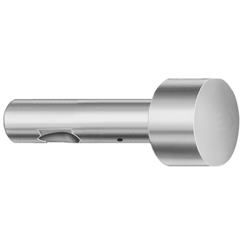
Ball Lock Ejector Punches - Light Duty, Inch, XCDP Coating
Ball Lock ejector punches - Light Duty, Inch, XCDP Coating are designed for controlled positioning in die and press tooling, using a ball-lock head for reliable part retention. The XCDP coating supports stable performance during routine production runs.
- Ball-lock retaining design improves alignment and consistent ejector action
- XCDP coating helps resist wear for extended punch service life
- Configurable tip shape options (X, R, K, O, H, L, J, N, V, Y, Z) match different cavity requirements
- Inch punch geometry available across common shank diameters for flexible die builds
Specifications
114 configurations available
| Tip Shape | D (Shank dia.) (in) | L (Length) (coded inch) | P Dimension (in) | W Dimension (in) | R Dimension (in) |
|---|---|---|---|---|---|
| H | 37 (0.3750") | 250 ~ 450 | 0.376 ~ 0.875 | 0.062 ~ 0.124 | - |
| H | 37 (0.3750") | 250 ~ 450 | 0.376 ~ 0.875 | 0.125 ~ 0.875 | - |
| H | 50 (0.5000") | 250 ~ 450 | 0.501 ~ 1.25 | 0.158 ~ 0.187 | - |
| H | 50 (0.5000") | 250 ~ 450 | 0.501 ~ 1.25 | 0.188 ~ 1.25 | - |
| H | 62 (0.6250") | 250 ~ 450 | 0.626 ~ 1.5 | 0.25 ~ 1.5 | - |
| H | 62 (0.6250") | 250 ~ 450 | 0.626 ~ 1.5 | 0.158 ~ 0.249 | - |
| H | 75 (0.7500") | 250 ~ 450 | 0.751 ~ 1.5 | 0.235 ~ 0.311 | - |
| H | 75 (0.7500") | 250 ~ 450 | 0.751 ~ 1.5 | 0.312 ~ 1.5 | - |
| H | 87 (0.8750") | 250 ~ 450 | 0.876 ~ 1.75 | 0.235 ~ 0.374 | - |
| H | 87 (0.8750") | 250 ~ 450 | 0.876 ~ 1.75 | 0.375 ~ 1.75 | - |
| H | 100 (1.0000") | 250 ~ 450 | 1.001 ~ 1.75 | 0.235 ~ 0.436 | - |
| H | 100 (1.0000") | 250 ~ 450 | 1.001 ~ 1.75 | 0.437 ~ 1.75 | - |
| J | 37 (0.3750") | 250 ~ 450 | 0.376 ~ 0.875 | 0.062 ~ 0.124 | - |
| J | 37 (0.3750") | 250 ~ 450 | 0.376 ~ 0.875 | 0.125 ~ 0.875 | - |
| J | 50 (0.5000") | 250 ~ 450 | 0.501 ~ 1.25 | 0.158 ~ 0.187 | - |
| J | 50 (0.5000") | 250 ~ 450 | 0.501 ~ 1.25 | 0.188 ~ 1.25 | - |
| J | 62 (0.6250") | 250 ~ 450 | 0.626 ~ 1.5 | 0.25 ~ 1.5 | - |
| J | 62 (0.6250") | 250 ~ 450 | 0.626 ~ 1.5 | 0.158 ~ 0.249 | - |
| J | 75 (0.7500") | 250 ~ 450 | 0.751 ~ 1.5 | 0.235 ~ 0.311 | - |
| J | 75 (0.7500") | 250 ~ 450 | 0.751 ~ 1.5 | 0.312 ~ 1.5 | - |
| J | 87 (0.8750") | 250 ~ 450 | 0.876 ~ 1.75 | 0.235 ~ 0.374 | - |
| J | 87 (0.8750") | 250 ~ 450 | 0.876 ~ 1.75 | 0.375 ~ 1.75 | - |
| J | 100 (1.0000") | 250 ~ 450 | 1.001 ~ 1.75 | 0.235 ~ 0.436 | - |
| J | 100 (1.0000") | 250 ~ 450 | 1.001 ~ 1.75 | 0.437 ~ 1.75 | - |
| K | 37 (0.3750") | 250 ~ 450 | 0.376 ~ 0.875 | 0.062 ~ 0.124 | 0.007 ~ 0.4375 |
| K | 37 (0.3750") | 250 ~ 450 | 0.376 ~ 0.875 | 0.125 ~ 0.875 | 0.007 ~ 0.4375 |
| K | 50 (0.5000") | 250 ~ 450 | 0.501 ~ 1.25 | 0.158 ~ 0.187 | 0.007 ~ 0.625 |
| K | 50 (0.5000") | 250 ~ 450 | 0.501 ~ 1.25 | 0.188 ~ 1.25 | 0.007 ~ 0.625 |
| K | 62 (0.6250") | 250 ~ 450 | 0.626 ~ 1.5 | 0.25 ~ 1.5 | 0.007 ~ 0.75 |
| K | 62 (0.6250") | 250 ~ 450 | 0.626 ~ 1.5 | 0.158 ~ 0.249 | 0.007 ~ 0.75 |
| K | 75 (0.7500") | 250 ~ 450 | 0.751 ~ 1.5 | 0.235 ~ 0.311 | 0.007 ~ 0.75 |
| K | 75 (0.7500") | 250 ~ 450 | 0.751 ~ 1.5 | 0.312 ~ 1.5 | 0.007 ~ 0.75 |
| K | 87 (0.8750") | 250 ~ 450 | 0.876 ~ 1.75 | 0.235 ~ 0.374 | 0.007 ~ 0.875 |
| K | 87 (0.8750") | 250 ~ 450 | 0.876 ~ 1.75 | 0.375 ~ 1.75 | 0.007 ~ 0.875 |
| K | 100 (1.0000") | 250 ~ 450 | 1.001 ~ 1.75 | 0.235 ~ 0.436 | 0.007 ~ 0.875 |
| K | 100 (1.0000") | 250 ~ 450 | 1.001 ~ 1.75 | 0.437 ~ 1.75 | 0.007 ~ 0.875 |
| L | 37 (0.3750") | 250 ~ 450 | 0.376 ~ 0.875 | 0.062 ~ 0.124 | - |
| L | 37 (0.3750") | 250 ~ 450 | 0.376 ~ 0.875 | 0.125 ~ 0.875 | - |
| L | 50 (0.5000") | 250 ~ 450 | 0.501 ~ 1.25 | 0.158 ~ 0.187 | - |
| L | 50 (0.5000") | 250 ~ 450 | 0.501 ~ 1.25 | 0.188 ~ 1.25 | - |
| L | 62 (0.6250") | 250 ~ 450 | 0.626 ~ 1.5 | 0.25 ~ 1.5 | - |
| L | 62 (0.6250") | 250 ~ 450 | 0.626 ~ 1.5 | 0.158 ~ 0.249 | - |
| L | 75 (0.7500") | 250 ~ 450 | 0.751 ~ 1.5 | 0.235 ~ 0.311 | - |
| L | 75 (0.7500") | 250 ~ 450 | 0.751 ~ 1.5 | 0.312 ~ 1.5 | - |
| L | 87 (0.8750") | 250 ~ 450 | 0.876 ~ 1.75 | 0.235 ~ 0.374 | - |
| L | 87 (0.8750") | 250 ~ 450 | 0.876 ~ 1.75 | 0.375 ~ 1.75 | - |
| L | 100 (1.0000") | 250 ~ 450 | 1.001 ~ 1.75 | 0.235 ~ 0.436 | - |
| L | 100 (1.0000") | 250 ~ 450 | 1.001 ~ 1.75 | 0.437 ~ 1.75 | - |
| N | 37 (0.3750") | 250 ~ 450 | - | 0.326 ~ 0.758 | - |
| N | 50 (0.5000") | 250 ~ 450 | - | 0.434 ~ 1.083 | - |
Product Guide
Application Scenarios+
Ball-lock ejector punches are used in die tooling and press systems where stable ejector positioning is critical during part release and blanking. The ball-lock retaining head helps maintain the punch-to-block relationship, reducing drift and promoting consistent ejection across production cycles.
These light-duty, inch-dimension punches are well suited for automotive connector and bracket die sets that run frequent short cycles. The XCDP coating supports wear resistance in routine blanking, helping keep punch edges and guiding performance steady as throughput increases.
They also fit consumer electronics and housing blanking applications that require reliable retention while switching tip shapes to match different cavity geometries. Select from multiple tip shapes (H, J, K, L, N, O, R, V, X, Y, Z) to tune interaction with the formed feature, improving repeatability in the ejection zone.
- Use in die cavities where consistent ejector action reduces scrap and rework
- Choose inch shank diameters to align with common press die builds
- Apply XCDP finish for improved service life under light-duty production wear
Material & Process Details+
This series specifies an XCDP coating for improved surface durability during die press service. While the exact base steel grade and heat treatment are not provided in the data set, the coating is intended to enhance wear resistance and maintain stable blanking performance over normal production runs.
In punch applications, the practical trade-off is that increasing surface durability helps resist abrasion and micro-wear at the cutting/working interface, but ultimate toughness and edge durability still depend on the underlying punch steel and its heat treatment. Since hardness values (e.g., HRC) and specific states (e.g., quenched & tempered, nitrided) are not listed here, qualification should be confirmed with the supplier’s material certificate for your exact part configuration.
- XCDP coating: designed to resist wear for stable punch operation
- Hardness and base-steel heat treatment: not specified in provided parameters
- If alternatives are offered, compare by coating vs. base-steel toughness for your wear vs. edge-failure risk profile
Sizing & Selection Guide+
To select the correct ball-lock ejector punch size, start with the die/tooling interface requirements, then match the punch to your cavity/core geometry. This series is available in inch shank diameter D values of 0.3750" (37), 0.5000" (50), 0.6250" (62), 0.7500" (75), 0.8750" (87), and 1.0000" (100).
Next, choose the L (coded inch length) between 250 ~ 450, which should be long enough to span your guide stack and allow safe engagement/retention in the ball-lock system without bottoming.
- Select Tip Shape (H, J, K, L, N, O, R, V, X, Y, Z) based on how the punch contacts your formed feature.
- Confirm P dimension within the available ranges: 0.376–0.875, 0.501–1.25, 0.626–1.5, 0.751–1.5, 0.876–1.75, or 1.001–1.75.
- Match the W dimension (available 0.062–0.867) and R (available 0.007–0.4375, 0.007–0.625, 0.007–0.75, or 0.007–0.875) to your cavity contact radius and clearance.
Tolerance and fit guidance is dependent on the die block pocket/guide design; verify your drawing callouts against the specific punch configuration since tolerances are not provided in the current data.
Frequently Asked Questions
Which shank diameter D options are available for this light-duty inch ball-lock ejector punch series?+
The series provides inch shank diameter D options of 0.3750" (37), 0.5000" (50), 0.6250" (62), 0.7500" (75), 0.8750" (87), and 1.0000" (100).
Select the diameter that matches your die tool guide/block bore requirements for stable alignment during ejection.
How do I choose the correct L length for ball-lock retention in my die build?+
This series lists L (coded inch length) in the range 250 ~ 450. Choose a length that covers your guide stack height and maintains engagement of the ball-lock system without causing interference or bottoming.
If your stack height changes with inserts, re-check L against the assembled tool height.
What tip shapes are offered, and when would I switch between them?+
Available Tip Shape options are H, J, K, L, N, O, R, V, X, Y, Z. Use different tip shapes to match the geometry of the cavity/core feature and the contact zone required for consistent ejection.
Switching tip shapes is typically driven by the formed part’s land/radius requirements rather than the ball-lock mechanism itself.
How do the P, W, and R dimensions relate to cavity contact and clearance?+
The configuration provides P ranges of 0.376–0.875, 0.501–1.25, 0.626–1.5, 0.751–1.5, 0.876–1.75, and 1.001–1.75, along with W values from 0.062–0.867 and R from 0.007–0.4375 up to 0.007–0.875 (depending on configuration).
Match these to the cavity contact profile and required clearance to avoid scraping or insufficient engagement during ejection.
What does the XCDP coating contribute to performance for light-duty die tooling?+
This series uses an XCDP coating intended to improve wear resistance and support stable blanking performance during routine production runs.
The dataset does not provide the underlying steel grade or target hardness (HRC), so hardness qualification should be confirmed for your exact punch configuration.
Related Products


Need Custom Specifications?
Our engineering team can help with custom configurations, material selection, and volume pricing.