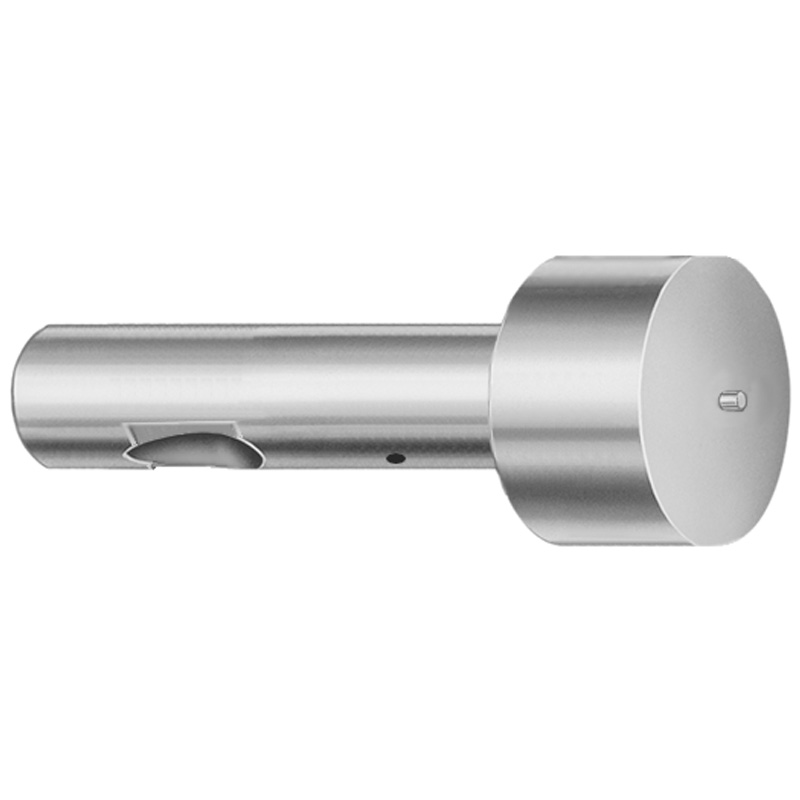
Ball Lock Ejector Punches - Light Duty, Inch, XNM Coating
Ball Lock Ejector Punches - Light Duty, Inch, XNM Coating (DAYTON) are designed for controlled retention during knockout operations in light-duty mold tooling. The coated surfaces help support stable wear behavior while delivering consistent ejection performance.
- Ball-lock punch body for positive retention and repeatable knockout
- XNM coating supports improved surface wear resistance in molding cycles
- Precision manufacturing for dependable fit with ball-lock tooling interfaces
- Typical use in tool & die assemblies requiring light-duty ejector action
Specifications
114 configurations available
| Tip Shape | D (Shank dia.) (in) | Jektole group | L (Length) (coded inch) | P Dimension (in) | W Dimension (in) | R Dimension (in) |
|---|---|---|---|---|---|---|
| H | 37 (0.3750") | J4 | 250 ~ 450 | 0.376 ~ 0.875 | 0.062 ~ 0.124 | - |
| H | 37 (0.3750") | J4 | 250 ~ 450 | 0.376 ~ 0.875 | 0.125 ~ 0.875 | - |
| H | 50 (0.5000") | J6 | 250 ~ 450 | 0.501 ~ 1.25 | 0.158 ~ 0.187 | - |
| H | 50 (0.5000") | J6 | 250 ~ 450 | 0.501 ~ 1.25 | 0.188 ~ 1.25 | - |
| H | 62 (0.6250") | J6 | 250 ~ 450 | 0.626 ~ 1.5 | 0.25 ~ 1.5 | - |
| H | 62 (0.6250") | J6 | 250 ~ 450 | 0.626 ~ 1.5 | 0.158 ~ 0.249 | - |
| H | 75 (0.7500") | J9 | 250 ~ 450 | 0.751 ~ 1.5 | 0.235 ~ 0.311 | - |
| H | 75 (0.7500") | J9 | 250 ~ 450 | 0.751 ~ 1.5 | 0.312 ~ 1.5 | - |
| H | 87 (0.8750") | J9 | 250 ~ 450 | 0.876 ~ 1.75 | 0.235 ~ 0.374 | - |
| H | 87 (0.8750") | J9 | 250 ~ 450 | 0.876 ~ 1.75 | 0.375 ~ 1.75 | - |
| H | 100 (1.0000") | J9 | 250 ~ 450 | 1.001 ~ 1.75 | 0.235 ~ 0.436 | - |
| H | 100 (1.0000") | J9 | 250 ~ 450 | 1.001 ~ 1.75 | 0.437 ~ 1.75 | - |
| J | 37 (0.3750") | J4 | 250 ~ 450 | 0.376 ~ 0.875 | 0.062 ~ 0.124 | - |
| J | 37 (0.3750") | J4 | 250 ~ 450 | 0.376 ~ 0.875 | 0.125 ~ 0.875 | - |
| J | 50 (0.5000") | J6 | 250 ~ 450 | 0.501 ~ 1.25 | 0.158 ~ 0.187 | - |
| J | 50 (0.5000") | J6 | 250 ~ 450 | 0.501 ~ 1.25 | 0.188 ~ 1.25 | - |
| J | 62 (0.6250") | J6 | 250 ~ 450 | 0.626 ~ 1.5 | 0.25 ~ 1.5 | - |
| J | 62 (0.6250") | J6 | 250 ~ 450 | 0.626 ~ 1.5 | 0.158 ~ 0.249 | - |
| J | 75 (0.7500") | J9 | 250 ~ 450 | 0.751 ~ 1.5 | 0.235 ~ 0.311 | - |
| J | 75 (0.7500") | J9 | 250 ~ 450 | 0.751 ~ 1.5 | 0.312 ~ 1.5 | - |
| J | 87 (0.8750") | J9 | 250 ~ 450 | 0.876 ~ 1.75 | 0.235 ~ 0.374 | - |
| J | 87 (0.8750") | J9 | 250 ~ 450 | 0.876 ~ 1.75 | 0.375 ~ 1.75 | - |
| J | 100 (1.0000") | J9 | 250 ~ 450 | 1.001 ~ 1.75 | 0.235 ~ 0.436 | - |
| J | 100 (1.0000") | J9 | 250 ~ 450 | 1.001 ~ 1.75 | 0.437 ~ 1.75 | - |
| K | 37 (0.3750") | J4 | 250 ~ 450 | 0.376 ~ 0.875 | 0.062 ~ 0.124 | 0.007 ~ 0.4375 |
| K | 37 (0.3750") | J4 | 250 ~ 450 | 0.376 ~ 0.875 | 0.125 ~ 0.875 | 0.007 ~ 0.4375 |
| K | 50 (0.5000") | J6 | 250 ~ 450 | 0.501 ~ 1.25 | 0.158 ~ 0.187 | 0.007 ~ 0.625 |
| K | 50 (0.5000") | J6 | 250 ~ 450 | 0.501 ~ 1.25 | 0.188 ~ 1.25 | 0.007 ~ 0.625 |
| K | 62 (0.6250") | J6 | 250 ~ 450 | 0.626 ~ 1.5 | 0.25 ~ 1.5 | 0.007 ~ 0.75 |
| K | 62 (0.6250") | J6 | 250 ~ 450 | 0.626 ~ 1.5 | 0.158 ~ 0.249 | 0.007 ~ 0.75 |
| K | 75 (0.7500") | J9 | 250 ~ 450 | 0.751 ~ 1.5 | 0.235 ~ 0.311 | 0.007 ~ 0.75 |
| K | 75 (0.7500") | J9 | 250 ~ 450 | 0.751 ~ 1.5 | 0.312 ~ 1.5 | 0.007 ~ 0.75 |
| K | 87 (0.8750") | J9 | 250 ~ 450 | 0.876 ~ 1.75 | 0.235 ~ 0.374 | 0.007 ~ 0.875 |
| K | 87 (0.8750") | J9 | 250 ~ 450 | 0.876 ~ 1.75 | 0.375 ~ 1.75 | 0.007 ~ 0.875 |
| K | 100 (1.0000") | J9 | 250 ~ 450 | 1.001 ~ 1.75 | 0.235 ~ 0.436 | 0.007 ~ 0.875 |
| K | 100 (1.0000") | J9 | 250 ~ 450 | 1.001 ~ 1.75 | 0.437 ~ 1.75 | 0.007 ~ 0.875 |
| L | 37 (0.3750") | J4 | 250 ~ 450 | 0.376 ~ 0.875 | 0.062 ~ 0.124 | - |
| L | 37 (0.3750") | J4 | 250 ~ 450 | 0.376 ~ 0.875 | 0.125 ~ 0.875 | - |
| L | 50 (0.5000") | J6 | 250 ~ 450 | 0.501 ~ 1.25 | 0.158 ~ 0.187 | - |
| L | 50 (0.5000") | J6 | 250 ~ 450 | 0.501 ~ 1.25 | 0.188 ~ 1.25 | - |
| L | 62 (0.6250") | J6 | 250 ~ 450 | 0.626 ~ 1.5 | 0.25 ~ 1.5 | - |
| L | 62 (0.6250") | J6 | 250 ~ 450 | 0.626 ~ 1.5 | 0.158 ~ 0.249 | - |
| L | 75 (0.7500") | J9 | 250 ~ 450 | 0.751 ~ 1.5 | 0.235 ~ 0.311 | - |
| L | 75 (0.7500") | J9 | 250 ~ 450 | 0.751 ~ 1.5 | 0.312 ~ 1.5 | - |
| L | 87 (0.8750") | J9 | 250 ~ 450 | 0.876 ~ 1.75 | 0.235 ~ 0.374 | - |
| L | 87 (0.8750") | J9 | 250 ~ 450 | 0.876 ~ 1.75 | 0.375 ~ 1.75 | - |
| L | 100 (1.0000") | J9 | 250 ~ 450 | 1.001 ~ 1.75 | 0.235 ~ 0.436 | - |
| L | 100 (1.0000") | J9 | 250 ~ 450 | 1.001 ~ 1.75 | 0.437 ~ 1.75 | - |
| N | 37 (0.3750") | J4 | 250 ~ 450 | - | 0.326 ~ 0.758 | - |
| N | 50 (0.5000") | J6 | 250 ~ 450 | - | 0.434 ~ 1.083 | - |
Product Guide
Application Scenarios+
Ball-lock ejector punches are used inside injection mold tooling to provide controlled retention during knockout, helping maintain stable punch position as the cavity opens. This light-duty, inch-based variant is well suited for applications where ejection loads are moderate and repeatability is required.
Tool & die assemblies: Commonly specified for press tooling and mold inserts that rely on a ball-lock interface for positive retention. The XNM coating is intended to support more consistent surface wear behavior across repeated molding cycles, helping preserve fit and ejection performance.
Electromechanical and consumer parts molds: For housings and covers produced in lighter duty runs, the variety of tip shapes (H through Z, including X-shaped tips) allows designers to match stripping geometry while keeping the ball retention function reliable.
Mixed-material insert molding: Where inserts create localized wear points, the coated contact surfaces help reduce friction-related degradation at the punch interface, supporting predictable knockout timing.
- Choose the appropriate tip shape to match the knockout/retention geometry.
- Use the listed inch shank diameters to fit standard ball-lock tooling bores.
Material & Process Details+
The provided specifications for this light-duty ball-lock ejector punch series focus on inch sizing and XNM coating; however, no steel grade or heat treatment state (e.g., pre-hardened, quenched & tempered, nitrided) is explicitly listed in the input data. Therefore, material hardness (HRC) and exact wear/toughness trade-offs cannot be stated from the available information.
What can be supported here is the functional role of XNM coating: it is applied to the punch surfaces to help improve surface wear resistance during repeated injection molding cycles. For engineers, this typically translates into better retention of dimensional stability and a more consistent ball-lock interface after service.
- XNM coating: promotes improved surface wear behavior at the contact regions.
- Unspecified substrate grade/heat treatment: hardness and toughness performance should be confirmed against supplier material certification for the specific series.
- If comparing coated vs. uncoated options, select coated variants when cycle life and interface wear are primary drivers.
Sizing & Selection Guide+
Start by matching the punch shank diameter (D) to the ball-lock interface bore in your mold base or ejector system. For this series, D is available in inch sizes: 0.3750 (37), 0.5000 (50), 0.6250 (62), 0.7500 (75), 0.8750 (87), and 1.0000 (100).
Next, confirm the required length (L): the coded inch length range is 250 ~ 450 (use the corresponding code-to-length mapping used in your tooling drawings or purchase spec sheet).
Then select the interface geometry dimensions that govern engagement and clearance:
- Tip shape: choose from H, J, K, L, N, O, R, V, X, Y, Z to match stripping contact form. The tip shape set includes an X-shaped option per the product page context.
- P dimension ranges: 0.376~0.875, 0.501~1.25, 0.626~1.5, 0.751~1.5, 0.876~1.75, 1.001~1.75 (select the range that matches your cavity/core and ball-lock depth requirements).
- W dimension: 0.062~0.867 and R dimension: 0.007~0.4375, 0.007~0.625, 0.007~0.75, 0.007~0.875—use these to control contact radius and seating behavior.
Because tolerance/fit values are not included in the input data, validate the final punch-to-bore clearance against your ball-lock standard and drawing tolerances. Tip engagement should be verified for the selected Jektole group (J4, J6, J9) to ensure consistent retention.
Frequently Asked Questions
Which shank diameter D sizes are available for this light-duty ball-lock ejector punch series?+
How do I choose between different tip shapes (H through Z, including X) for knockout performance?+
What does the XNM coating contribute for tool life in light-duty injection molding cycles?+
What length options are available, and how should L be matched to the mold stackup?+
How do P, W, and R dimensions affect ball-lock engagement in the J4/J6/J9 groups?+
Related Products


Need Custom Specifications?
Our engineering team can help with custom configurations, material selection, and volume pricing.