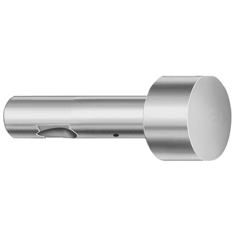
Ball Lock Ejector Punches - Light Duty, Inch
Ball Lock Ejector Punches - Light Duty, Inch are designed for controlled part release in small die configurations. The XVP coating helps reduce friction and resist wear during repeated cycles, supporting stable ejection performance.
- Point larger than shank ball-lock geometry for reliable locating during ejection
- XVP coating to improve surface durability under repeated punch cycles
- Dimensional coding supports consistent fit for standard fixture workflows
- Suitable for light-duty stamping and die tooling where precise part release matters
Specifications
114 configurations available
| Tip Shape | D (Shank dia.) (in) | L (Length) (coded inch) | P Dimension (in) | W Dimension (in) | R Dimension (in) |
|---|---|---|---|---|---|
| H | 37 (0.3750") | 250 ~ 450 | 0.376 ~ 0.875 | 0.062 ~ 0.124 | - |
| H | 37 (0.3750") | 250 ~ 450 | 0.376 ~ 0.875 | 0.125 ~ 0.875 | - |
| H | 50 (0.5000") | 250 ~ 450 | 0.501 ~ 1.25 | 0.158 ~ 0.187 | - |
| H | 50 (0.5000") | 250 ~ 450 | 0.501 ~ 1.25 | 0.188 ~ 1.25 | - |
| H | 62 (0.6250") | 250 ~ 450 | 0.626 ~ 1.5 | 0.25 ~ 1.5 | - |
| H | 62 (0.6250") | 250 ~ 450 | 0.626 ~ 1.5 | 0.158 ~ 0.249 | - |
| H | 75 (0.7500") | 250 ~ 450 | 0.751 ~ 1.5 | 0.235 ~ 0.311 | - |
| H | 75 (0.7500") | 250 ~ 450 | 0.751 ~ 1.5 | 0.312 ~ 1.5 | - |
| H | 87 (0.8750") | 250 ~ 450 | 0.876 ~ 1.75 | 0.235 ~ 0.374 | - |
| H | 87 (0.8750") | 250 ~ 450 | 0.876 ~ 1.75 | 0.375 ~ 1.75 | - |
| H | 100 (1.0000") | 250 ~ 450 | 1.001 ~ 1.75 | 0.235 ~ 0.436 | - |
| H | 100 (1.0000") | 250 ~ 450 | 1.001 ~ 1.75 | 0.437 ~ 1.75 | - |
| J | 37 (0.3750") | 250 ~ 450 | 0.376 ~ 0.875 | 0.062 ~ 0.124 | - |
| J | 37 (0.3750") | 250 ~ 450 | 0.376 ~ 0.875 | 0.125 ~ 0.875 | - |
| J | 50 (0.5000") | 250 ~ 450 | 0.501 ~ 1.25 | 0.158 ~ 0.187 | - |
| J | 50 (0.5000") | 250 ~ 450 | 0.501 ~ 1.25 | 0.188 ~ 1.25 | - |
| J | 62 (0.6250") | 250 ~ 450 | 0.626 ~ 1.5 | 0.25 ~ 1.5 | - |
| J | 62 (0.6250") | 250 ~ 450 | 0.626 ~ 1.5 | 0.158 ~ 0.249 | - |
| J | 75 (0.7500") | 250 ~ 450 | 0.751 ~ 1.5 | 0.235 ~ 0.311 | - |
| J | 75 (0.7500") | 250 ~ 450 | 0.751 ~ 1.5 | 0.312 ~ 1.5 | - |
| J | 87 (0.8750") | 250 ~ 450 | 0.876 ~ 1.75 | 0.235 ~ 0.374 | - |
| J | 87 (0.8750") | 250 ~ 450 | 0.876 ~ 1.75 | 0.375 ~ 1.75 | - |
| J | 100 (1.0000") | 250 ~ 450 | 1.001 ~ 1.75 | 0.235 ~ 0.436 | - |
| J | 100 (1.0000") | 250 ~ 450 | 1.001 ~ 1.75 | 0.437 ~ 1.75 | - |
| K | 37 (0.3750") | 250 ~ 450 | 0.376 ~ 0.875 | 0.062 ~ 0.124 | 0.007 ~ 0.4375 |
| K | 37 (0.3750") | 250 ~ 450 | 0.376 ~ 0.875 | 0.125 ~ 0.875 | 0.007 ~ 0.4375 |
| K | 50 (0.5000") | 250 ~ 450 | 0.501 ~ 1.25 | 0.158 ~ 0.187 | 0.007 ~ 0.625 |
| K | 50 (0.5000") | 250 ~ 450 | 0.501 ~ 1.25 | 0.188 ~ 1.25 | 0.007 ~ 0.625 |
| K | 62 (0.6250") | 250 ~ 450 | 0.626 ~ 1.5 | 0.25 ~ 1.5 | 0.007 ~ 0.75 |
| K | 62 (0.6250") | 250 ~ 450 | 0.626 ~ 1.5 | 0.158 ~ 0.249 | 0.007 ~ 0.75 |
| K | 75 (0.7500") | 250 ~ 450 | 0.751 ~ 1.5 | 0.235 ~ 0.311 | 0.007 ~ 0.75 |
| K | 75 (0.7500") | 250 ~ 450 | 0.751 ~ 1.5 | 0.312 ~ 1.5 | 0.007 ~ 0.75 |
| K | 87 (0.8750") | 250 ~ 450 | 0.876 ~ 1.75 | 0.235 ~ 0.374 | 0.007 ~ 0.875 |
| K | 87 (0.8750") | 250 ~ 450 | 0.876 ~ 1.75 | 0.375 ~ 1.75 | 0.007 ~ 0.875 |
| K | 100 (1.0000") | 250 ~ 450 | 1.001 ~ 1.75 | 0.235 ~ 0.436 | 0.007 ~ 0.875 |
| K | 100 (1.0000") | 250 ~ 450 | 1.001 ~ 1.75 | 0.437 ~ 1.75 | 0.007 ~ 0.875 |
| L | 37 (0.3750") | 250 ~ 450 | 0.376 ~ 0.875 | 0.062 ~ 0.124 | - |
| L | 37 (0.3750") | 250 ~ 450 | 0.376 ~ 0.875 | 0.125 ~ 0.875 | - |
| L | 50 (0.5000") | 250 ~ 450 | 0.501 ~ 1.25 | 0.158 ~ 0.187 | - |
| L | 50 (0.5000") | 250 ~ 450 | 0.501 ~ 1.25 | 0.188 ~ 1.25 | - |
| L | 62 (0.6250") | 250 ~ 450 | 0.626 ~ 1.5 | 0.25 ~ 1.5 | - |
| L | 62 (0.6250") | 250 ~ 450 | 0.626 ~ 1.5 | 0.158 ~ 0.249 | - |
| L | 75 (0.7500") | 250 ~ 450 | 0.751 ~ 1.5 | 0.235 ~ 0.311 | - |
| L | 75 (0.7500") | 250 ~ 450 | 0.751 ~ 1.5 | 0.312 ~ 1.5 | - |
| L | 87 (0.8750") | 250 ~ 450 | 0.876 ~ 1.75 | 0.235 ~ 0.374 | - |
| L | 87 (0.8750") | 250 ~ 450 | 0.876 ~ 1.75 | 0.375 ~ 1.75 | - |
| L | 100 (1.0000") | 250 ~ 450 | 1.001 ~ 1.75 | 0.235 ~ 0.436 | - |
| L | 100 (1.0000") | 250 ~ 450 | 1.001 ~ 1.75 | 0.437 ~ 1.75 | - |
| N | 37 (0.3750") | 250 ~ 450 | - | 0.326 ~ 0.758 | - |
| N | 50 (0.5000") | 250 ~ 450 | - | 0.434 ~ 1.083 | - |
Product Guide
Application Scenarios+
These light-duty ball lock ejector punches are used to drive controlled part release in compact die sets and small injection tooling where consistent locating during ejection is critical. The ball-lock geometry, including a tip larger than the shank, helps maintain stable positioning as the punch moves through the cycle.
- Compact stamping/die inserts: The XVP coating reduces friction and improves surface durability under repeated punch cycles, supporting smooth ejection in smaller die configurations.
- Small molded connectors and housings: Use the series where a reliable ejector action is needed for fine features; the dimensional coding supports repeatable fit with standard fixture workflows.
- Light-duty automation tooling: The range of inch shank diameters and coded lengths enables selection to match cavity/core ejection layouts while maintaining controlled release.
Overall, this variant is suited for applications that require predictable part release with wear-resistant, low-friction sliding behavior rather than heavy-duty impact performance.
Material & Process Details+
The provided specifications emphasize an XVP coating for improved wear resistance and smooth ejection, which directly supports repeated-cycle durability at the punch surface. However, the input data does not list a specific steel grade or a stated heat-treatment condition (e.g., quenched & tempered, nitrided), so hardness (HRC) and base-material toughness trade-offs cannot be stated from the supplied information.
From a manufacturing standpoint, ball lock punches are typically finished to maintain tight geometry at the ball-lock interface (tip and shank relationship), then coated to reduce friction and resist wear during ejection strokes. The coating’s primary role is to lower sliding friction and help prevent surface degradation during high-frequency cycling.
- XVP coating: Improves wear resistance and smooth ejection behavior.
- Material/heat treatment: Not specified in the provided dataset; confirm steel grade and heat-treatment state for hardness and toughness requirements.
Sizing & Selection Guide+
Select dimensions by matching your ejection travel and the clearance/fit requirements in the mold or die insert. This series is defined by L (Length) coded in the range 250 ~ 450 (coded inch), while D (shank diameter) is available at 0.3750”, 0.5000”, 0.6250”, 0.7500”, 0.8750”, 1.0000”.
- Step 1—Choose D (shank dia.): Match the shank to your guide/bushing bore ID and alignment needs; use the inch diameter that corresponds to your fixture standards.
- Step 2—Choose L (length): Confirm required stroke and stick-out for the cavity/core interface using the coded 250 ~ 450 length options.
- Step 3—Match ball-lock geometry: Ensure tip shape (H/J/K/L/N/O/R/V/X/Y/Z) matches your locating requirements. Use the provided variable ranges for P (0.376~0.875, 0.501~1.25, 0.626~1.5, 0.751~1.5, 0.876~1.75, 1.001~1.75 in) and W (0.062~0.867 in), plus the relevant R (0.007~0.4375, 0.007~0.625, 0.007~0.75, 0.007~0.875 in) range.
Tolerance note: The dataset does not provide explicit tolerance values; verify tolerance class compatibility with your ejector guide system and mating ball-lock pocket dimensions before finalizing selection.
Frequently Asked Questions
Which tip shape options (H, J, K, …) should I select for a specific ball-lock ejector pocket geometry?+
This series supports multiple Tip Shape codes: H, J, K, L, N, O, R, V, X, Y, Z. Choose the tip shape that matches the locating profile required by your ball-lock pocket so the tip larger-than-shank geometry can consistently position the ejector during release.
For best results, coordinate the tip shape selection with your required P, W, and R dimensional ranges so the contact surfaces align with your die insert design.
How do I match the ejector punch length to my required ejection travel using the coded L range (250~450)?+
The punch L is specified as 250 ~ 450 (coded inch). Use this coded length to set the required stick-out and engagement with the part as your cavity/core ejector plan dictates.
Because the dataset does not list stroke or protrusion tolerances, confirm that the coded length provides sufficient engagement without over-travel in your ejector layout.
What shank diameter (D) range is available, and how should it relate to guide/bushing bore sizing?+
Available D (shank dia.) values are 0.3750”, 0.5000”, 0.6250”, 0.7500”, 0.8750”, and 1.0000”. Select the D that matches the bore size of your ejector guide/bushing system to maintain alignment through repeated cycles.
The input data provides dimensions and ranges but not tolerance; verify clearance and fit against your standard fixture specifications before finalizing.
What does the XVP coating do for light-duty ejector performance?+
The metadata states this variant includes an XVP coating for improved wear resistance and smooth ejection. In practice, this coating is intended to reduce friction during repeated punch cycles, helping preserve the ball-lock interface and ejection stability.
It is particularly suitable for light-duty die/tooling where controlled part release matters more than heavy impact load.
If I need tighter dimensional matching, which variables should I check beyond D and L?+
Beyond D and L, the dataset provides several geometry variables you should confirm for compatibility with your mold cavity/core: P (0.376~0.875, 0.501~1.25, 0.626~1.5, 0.751~1.5, 0.876~1.75, 1.001~1.75 in), W (0.062~0.867 in), and R (0.007~0.4375, 0.007~0.625, 0.007~0.75, 0.007~0.875 in).
Also verify Tip Shape selection (H/J/K/L/N/O/R/V/X/Y/Z) so the locating profile aligns with your ball-lock pocket design.
Related Products


Need Custom Specifications?
Our engineering team can help with custom configurations, material selection, and volume pricing.