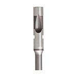
SKH51 Steel Ball Lock Ejector Punches - Heavy Load, Wrench Flat
Ball Lock Ejector Punches - Heavy Load, Wrench Flat (SKH51 steel) are designed for stable ball-lock action and efficient ejection in demanding die and mold setups. The HW coating helps reduce wear during high-cycle production.
- Shoulder punch form with wrench flat improves handling and consistent seating during assembly
- SKH51 steel construction with HW coating supports abrasion resistance for heavy-duty runs
- Factory-grade finishing supports repeatable fit for ball-lock tool interfaces
- Used in progressive dies, injection molds, and other tooling requiring dependable extraction force
Specifications
360 configurations available
| Tip Shape | B (Tip length) (mm) | D (Shank diameter) (mm) | L (L Dimension) (mm) | LC (Full length alteration) (mm) | P (Tip dimension) (mm) | PC (Tip dimension alteration) (mm) | W (Tip dimension) (mm) | WC (Tip dimension alteration) (mm) | R (Tip dimension) (mm) | type |
|---|---|---|---|---|---|---|---|---|---|---|
| Round | L | 10 | 80 ~ 100 | - | 3 ~ 9.97 | - | - | - | - | - |
| Round | L | 10 | 80 ~ 100 | - | - | 1.5 ~ 2.99 | - | - | - | - |
| Round | L | 10 | - | 52 ~ 99.9 | 3 ~ 9.97 | - | - | - | - | - |
| Round | L | 10 | - | 52 ~ 99.9 | - | 1.5 ~ 2.99 | - | - | - | - |
| Round | L | 13 | 80 ~ 100 | - | 6 ~ 12.97 | - | - | - | - | - |
| Round | L | 13 | 80 ~ 100 | - | - | 3 ~ 5.99 | - | - | - | - |
| Round | L | 13 | - | 52 ~ 99.9 | 6 ~ 12.97 | - | - | - | - | - |
| Round | L | 13 | - | 52 ~ 99.9 | - | 3 ~ 5.99 | - | - | - | - |
| Round | L | 16 | 80 ~ 100 | - | 10 ~ 15.97 | - | - | - | - | - |
| Round | L | 16 | 80 ~ 100 | - | - | 5 ~ 9.99 | - | - | - | - |
| Round | L | 16 | - | 52 ~ 99.9 | 10 ~ 15.97 | - | - | - | - | - |
| Round | L | 16 | - | 52 ~ 99.9 | - | 5 ~ 9.99 | - | - | - | - |
| Round | L | 20 | 80 ~ 100 | - | 13 ~ 19.97 | - | - | - | - | - |
| Round | L | 20 | 80 ~ 100 | - | - | 6.5 ~ 12.99 | - | - | - | - |
| Round | L | 20 | - | 52 ~ 99.9 | 13 ~ 19.97 | - | - | - | - | - |
| Round | L | 20 | - | 52 ~ 99.9 | - | 6.5 ~ 12.99 | - | - | - | - |
| Round | L | 25 | 80 ~ 100 | - | 18 ~ 24.97 | - | - | - | - | - |
| Round | L | 25 | 80 ~ 100 | - | - | 9 ~ 17.99 | - | - | - | - |
| Round | L | 25 | - | 52 ~ 99.9 | 18 ~ 24.97 | - | - | - | - | - |
| Round | L | 25 | - | 52 ~ 99.9 | - | 9 ~ 17.99 | - | - | - | - |
| Round | S | 10 | 71 ~ 100 | - | 3 ~ 9.97 | - | - | - | - | - |
| Round | S | 10 | 71 ~ 100 | - | - | 1.5 ~ 2.99 | - | - | - | - |
| Round | S | 10 | - | 52 ~ 99.9 | 3 ~ 9.97 | - | - | - | - | - |
| Round | S | 10 | - | 52 ~ 99.9 | - | 1.5 ~ 2.99 | - | - | - | - |
| Round | S | 13 | 71 ~ 100 | - | 6 ~ 12.97 | - | - | - | - | - |
| Round | S | 13 | 71 ~ 100 | - | - | 3 ~ 5.99 | - | - | - | - |
| Round | S | 13 | - | 52 ~ 99.9 | 6 ~ 12.97 | - | - | - | - | - |
| Round | S | 13 | - | 52 ~ 99.9 | - | 3 ~ 5.99 | - | - | - | - |
| Round | S | 16 | 71 ~ 100 | - | 10 ~ 15.97 | - | - | - | - | - |
| Round | S | 16 | 71 ~ 100 | - | - | 5 ~ 9.99 | - | - | - | - |
| Round | S | 16 | - | 52 ~ 99.9 | 10 ~ 15.97 | - | - | - | - | - |
| Round | S | 16 | - | 52 ~ 99.9 | - | 5 ~ 9.99 | - | - | - | - |
| Round | S | 20 | 71 ~ 100 | - | 13 ~ 19.97 | - | - | - | - | - |
| Round | S | 20 | 71 ~ 100 | - | - | 6.5 ~ 12.99 | - | - | - | - |
| Round | S | 20 | - | 52 ~ 99.9 | 13 ~ 19.97 | - | - | - | - | - |
| Round | S | 20 | - | 52 ~ 99.9 | - | 6.5 ~ 12.99 | - | - | - | - |
| Round | S | 25 | 71 ~ 100 | - | 18 ~ 24.97 | - | - | - | - | - |
| Round | S | 25 | 71 ~ 100 | - | - | 9 ~ 17.99 | - | - | - | - |
| Round | S | 25 | - | 52 ~ 99.9 | 18 ~ 24.97 | - | - | - | - | - |
| Round | S | 25 | - | 52 ~ 99.9 | - | 9 ~ 17.99 | - | - | - | - |
| Rectangle | L | 10 | 80 ~ 100 | - | 2.5 ~ 9.9 | - | 2.5 ~ 9.9 | - | - | - |
| Rectangle | L | 10 | 80 ~ 100 | - | 2.5 ~ 9.9 | - | - | 1.25 ~ 2.49 | - | - |
| Rectangle | L | 10 | 80 ~ 100 | - | - | 1.25 ~ 2.49 | 2.5 ~ 9.9 | - | - | - |
| Rectangle | L | 10 | 80 ~ 100 | - | - | 1.25 ~ 2.49 | - | 1.25 ~ 2.49 | - | - |
| Rectangle | L | 10 | - | 52 ~ 99.9 | 2.5 ~ 9.9 | - | 2.5 ~ 9.9 | - | - | - |
| Rectangle | L | 10 | - | 52 ~ 99.9 | 2.5 ~ 9.9 | - | - | 1.25 ~ 2.49 | - | - |
| Rectangle | L | 10 | - | 52 ~ 99.9 | - | 1.25 ~ 2.49 | 2.5 ~ 9.9 | - | - | - |
| Rectangle | L | 10 | - | 52 ~ 99.9 | - | 1.25 ~ 2.49 | - | 1.25 ~ 2.49 | - | - |
| Rectangle | L | 13 | 80 ~ 100 | - | 3 ~ 12.9 | - | 3 ~ 12.9 | - | - | - |
| Rectangle | L | 13 | 80 ~ 100 | - | 3 ~ 12.9 | - | - | 1.5 ~ 2.99 | - | - |
Product Guide
Application Scenarios+
These ball-lock ejector punches are used in injection molding and die tooling where a repeatable ball-lock action is required to stabilize extraction. The heavy-load SKH51 steel body helps maintain consistent seating under high cycle stress, while the HW coating improves wear resistance for long production runs.
- Automotive and appliance housings: In multi-part mold cavities, they support dependable ejection forces and reduce intermittent lock-up caused by abrasion at the ball-lock interface.
- Consumer electronics snap-fit components: The wrench flat assists handling and alignment during tool assembly, helping engineers achieve consistent fit during periodic maintenance.
- Progressive dies and transfer tooling: Round/rectangular/oblong tip options allow tuning for extraction geometry while preserving ball-lock stability during frequent indexing.
With multiple shank diameters (10–25 mm) and selectable tip forms, this variant is suited for projects that prioritize extraction reliability and interface durability.
Material & Process Details+
SKH51 tool steel is used for its balance of wear resistance and toughness in sliding/impact regions common to ejector systems. This punch is finished with an HW coating intended to further improve abrasion resistance, helping reduce material loss during high-cycle extraction.
In mold tooling practice, SKH51 is commonly heat-treated to achieve a hard surface for wear durability, trading off some toughness to improve tool life at the contact areas. For design trade-offs, higher surface hardness increases resistance to scuffing and galling, while excessively hard conditions can be more sensitive to edge chipping if shock loading is extreme.
- Hardness: Final HRC is not specified in the provided data; confirm with your purchase documentation for exact target value.
- Manufacturing: Steel punches are typically precision ground to control the shank and tip dimensions, then coated after machining to maintain fit where ball-lock interfaces engage.
- Coating effect: The HW layer improves wear resistance, supporting longer runs compared to uncoated tooling under similar loads.
Sizing & Selection Guide+
Select sizing by matching the shank diameter (D), overall length, and tip geometry to the cavity/core and the ball-lock ejector guide space. Available D values are 10, 13, 16, 20, and 25 mm, so choose the diameter that fits the mating ejector/bushing bore without binding.
- Overall length (L): choose from 80–100 mm or 71–100 mm depending on your ejector stack-up and required stroke clearance.
- Full length alteration (LC): available in the range 52–99.9 mm; use this to fine-tune for tool layout while maintaining adequate engagement length.
- Tip geometry: select Tip Shape (Round, Rectangle, Oblong, Double Flatted Round, Radius Rectangle) and corresponding P, PC, W, WC, and R ranges to match the extraction contact area.
Because interface fit is critical for ball-lock action, keep an eye on functional clearances and assembly tolerances in the mating parts; confirm that the selected tip/body dimensions align with your tool’s locking and ejection alignment requirements. Dimensions listed as variable are configurable within the stated ranges.
Frequently Asked Questions
Which shank diameter (D) should I choose for a ball-lock ejector punch to match my ejector guide bore?+
Select D from the available options: 10, 13, 16, 20, or 25 mm. Use the bore size of your ejector guide/bushing and confirm the required working clearance for ball-lock engagement. If you are constrained by stack-up length, also verify the selected L (80–100 or 71–100 mm) works with your ejection stroke.
How do I pick the correct tip shape and tip dimensions (P/W/R) for reliable extraction geometry?+
Choose the Tip Shape (Round, Rectangle, Oblong, Double Flatted Round, or Radius Rectangle) based on the part surface and extraction contact pattern. Then match P (2.5–18 mm) and W (2.5–6 mm) to the available clearance and contact area. Use the appropriate R range (0.15 up to 12.44 mm depending on variant) to control corner radii for reduced stress concentration.
What does the wrench flat option improve during mold assembly or maintenance?+
The wrench flat (specified for this variant) improves handling and consistent seating during assembly of the ball-lock ejector system. It helps technicians apply controlled torque/alignment when installing or removing the punch. This reduces misalignment risk that can otherwise affect ball-lock stability and extraction repeatability.
How does SKH51 steel with an HW coating affect tool wear in high-cycle ejection?+
This series specifies SKH51 steel plus an HW coating intended to enhance wear resistance at the regions exposed to abrasion during extraction. In heavy-load applications, the coating can reduce surface degradation and help maintain consistent functional fit over time. Final hardness and exact heat treatment level (HRC) are not provided here, so confirm those values in the supplier documentation for your target wear life.
How should I use LC (full length alteration) when configuring ejector stack-up constraints?+
Use LC within 52–99.9 mm to adjust the punch’s full length to your tool’s ejector stack-up and available space. Pair LC selection with the required L range (80–100 or 71–100 mm) so you retain adequate engagement length for ball-lock function. Validate that the adjusted length maintains clearances for ejection travel and prevents interference with surrounding components.
Related Products


Need Custom Specifications?
Our engineering team can help with custom configurations, material selection, and volume pricing.